Understanding Clutch Drag and Release Failure
Clutch drag is one of the most frustrating drivetrain symptoms a driver can experience. It manifests as grinding when shifting into gear (especially reverse or first), difficulty finding neutral, and a vehicle that creeps forward even with the clutch pedal fully depressed to the floor. At its core, clutch drag means the friction disc is not fully disengaging from the flywheel. The transmission input shaft continues to spin, driven by the engine's rotational inertia, causing gear clash during synchronization attempts.
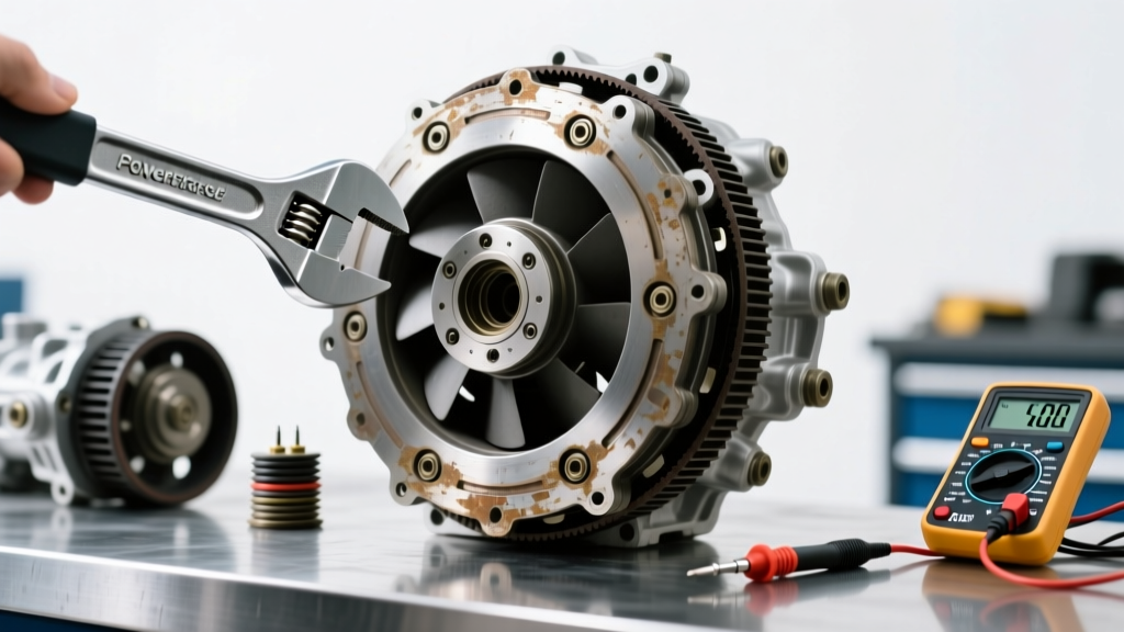
While warped friction discs, swollen hydraulic hoses, or a failing pilot bearing can cause drag, the most common culprit is improper release bearing travel. When the mechanical or hydraulic linkage lacks the correct geometry, the throw-out bearing (TOB) runs out of forward travel before it can push the diaphragm spring fingers past their over-center toggle point. To resolve this, technicians rely on a precision clutch adjustment tool to dial in the exact free-play and over-travel specifications required for complete disengagement.
The Physics of Diaphragm Spring Over-Travel
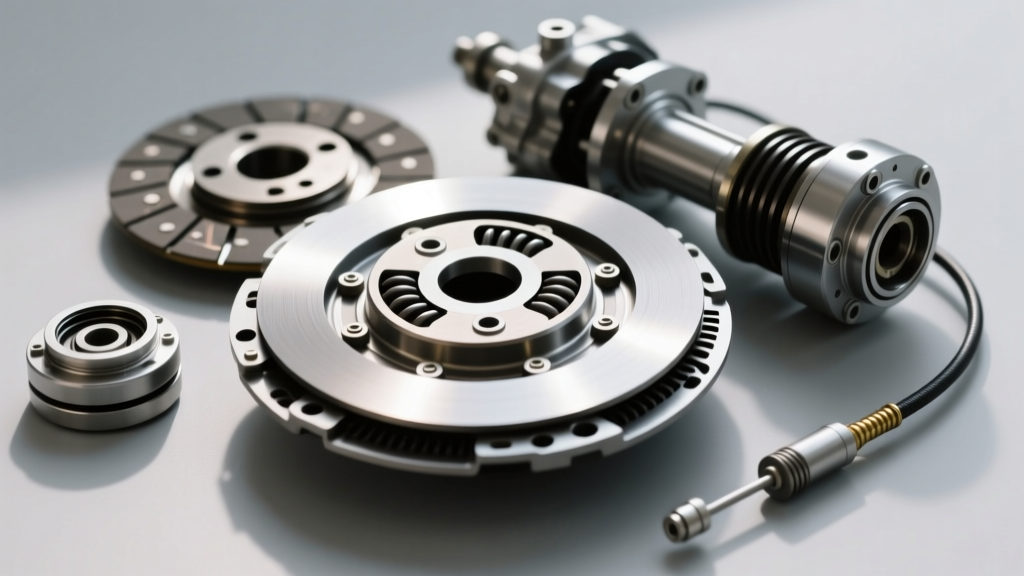
Modern clutches utilize a diaphragm spring. As the TOB presses against the spring fingers, the clamping load decreases. However, if the TOB travels too far past the flat point of the spring, the mechanical advantage reverses, and the clamping load actually begins to increase again. This phenomenon, known as over-travel, is a primary cause of release failure in high-performance applications. Conversely, excessive free-play prevents the TOB from reaching the flat point entirely. Using a dedicated clutch adjustment tool ensures the release mechanism operates strictly within the manufacturer's engineered window, typically between 0.050 inches and 0.120 inches of total TOB travel.
Required Equipment and Clutch Adjustment Tool Selection
Before crawling under the vehicle or reaching into the engine bay, you must select the correct clutch adjustment tool for your specific actuation system. Cable-actuated systems require physical tensioning devices, while hydraulic systems require precision measurement gauges and pushrod adjusters.
| System Type | Adjustment Tool / Part | Part Number Example | 2026 Avg. Cost |
|---|---|---|---|
| Cable (Firewall) | Billet Firewall Adjuster | Maximum Motorsports MM51-1 | $75 - $95 |
| Cable (Underdash) | Quadrant & Pawl Kit | Steeda 555-7003 | $110 - $140 |
| Hydraulic (External) | Adjustable Pushrod & Feeler Gauge | McLeod 139303 | $45 - $65 |
| Hydraulic (Internal) | Dial Indicator with Magnetic Base | Any Precision 0.001' Dial | $35 - $60 |
| Hydraulic (Bleeding) | Power Bleeder Kit | Motive Products 0107 | $55 - $70 |
Step-by-Step: Adjusting Cable-Actuated Clutches
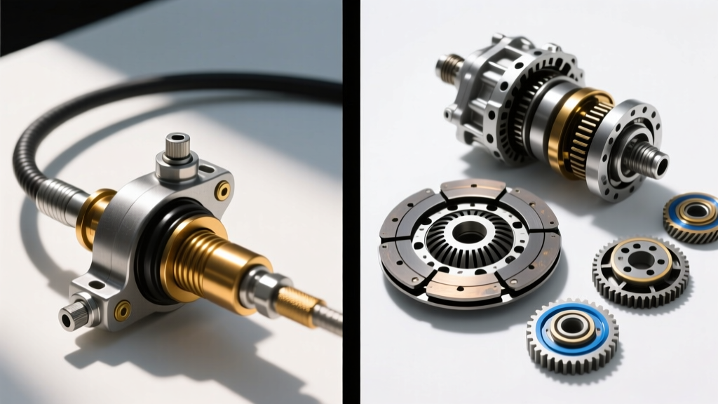
Cable clutches, commonly found in classic muscle cars, Honda K-Series platforms, and older Ford Mustangs, are highly susceptible to cable stretch and firewall flex. Over time, the cable housing compresses, robbing the system of critical release travel. Installing a billet firewall adjuster serves as both a permanent repair and an highly effective clutch adjustment tool.
Step 1: Inspect and Prep the Cable Routing
Before adjusting, verify the cable housing is securely seated in its rubber grommets at both the firewall and the bellhousing. A loose housing will absorb pedal travel. Check the cable wire itself for fraying. If the inner wire shows any 'bird-caging' (strands separating), replace the cable immediately. Lubricate the inner wire with a dedicated PTFE cable lube to reduce pedal effort.
Step 2: Install the Firewall Adjuster
Remove the stock plastic or stamped-steel firewall grommet. Thread the billet firewall adjuster into the firewall opening. Most aftermarket adjusters use a dual-nut locking system. Thread the adjuster all the way inward to start with a baseline of zero tension.
Step 3: Set the Baseline Free-Play
With the transmission in neutral and the engine off, have an assistant press the clutch pedal. Use your clutch adjustment tool (the knurled adjuster knob) to thread the cable outward until you feel resistance against the diaphragm spring fingers. This is the 'zero lash' point. From this point, back the adjuster off (inward) exactly 1 to 1.5 full turns. This provides approximately 1/8-inch of free-play at the TOB, preventing premature release bearing wear while ensuring full disengagement.
Step 4: Lock and Verify
Hold the adjuster knob firmly in place and tighten the locking jam nut against the firewall to a torque spec of 15 lb-ft. Depress the pedal multiple times to seat the cable, then re-check the free-play. The pedal should engage roughly 1 to 1.5 inches from the top of its travel.
Step-by-Step: Calibrating Hydraulic Pushrod Systems
Hydraulic systems, standard on modern manual transmissions like the Tremec T56 Magnum, Ford MT-82, and Porsche G50, rely on fluid displacement. While many modern internal hydraulic throw-out bearings are non-adjustable, external slave cylinders and adjustable master cylinder pushrods require precise calibration using a feeler gauge or dial indicator as your primary clutch adjustment tool.
Step 1: Measure Master Cylinder Pushrod Free-Play
Locate the master cylinder pushrod under the dashboard or in the engine bay (depending on the pedal box design). There must be a slight amount of free-play (typically 0.020 to 0.040 inches) between the pedal arm and the pushrod before it begins depressing the master cylinder piston. If there is zero free-play, the master cylinder piston will block the fluid return port, leading to a locked hydraulic system and severe clutch drag. Adjust the clevis or eccentric pedal stop to achieve this gap.
Step 2: Set Slave Cylinder Pushrod Clearance (External Slaves)
For transmissions utilizing an external slave cylinder and a traditional clutch fork (such as the GM LS/T56 swap combinations), the gap between the slave pushrod and the clutch fork is critical. According to Tremec's official service documentation, excessive gap results in incomplete disengagement, while zero gap causes the TOB to ride constantly on the diaphragm spring, leading to catastrophic bearing failure within 1,000 miles.
- Remove the rubber dust boot from the slave cylinder pushrod.
- Insert a 0.060-inch feeler gauge between the pushrod tip and the clutch fork dimple.
- Adjust the threaded pushrod (your mechanical clutch adjustment tool) until the 0.060-inch gauge slides through with a slight drag, but a 0.080-inch gauge will not fit.
- Tighten the pushrod jam nut to 18 lb-ft, applying a drop of blue Loctite 242 to the threads to prevent vibration-induced backing out.
Step 3: Bleed the Hydraulic System
Air trapped in the hydraulic lines acts as a compressible sponge, robbing the TOB of its required travel. Gravity bleeding is rarely sufficient for modern high-pressure systems. Attach a power bleeder to the master cylinder reservoir, pressurize it to 15 PSI, and open the slave cylinder bleeder screw. Allow fresh DOT 4 fluid (such as Motul RBF 600, which boasts a dry boiling point of 626°F) to flow until no micro-bubbles are visible. Close the bleeder screw to a torque of 7 lb-ft to avoid stripping the delicate brass threads.
Advanced Troubleshooting: When the Adjustment Tool Isn't Enough
If you have utilized your clutch adjustment tool to achieve perfect free-play and over-travel specifications, but the transmission still grinds into gear, the issue lies inside the bellhousing. At this stage, further external adjustment will only result in bent clutch forks or blown slave cylinder seals.
Expert Diagnostic Tip: Before pulling the transmission, perform the 'Rev-Match Spin Test'. With the engine off, put the car in 3rd gear and depress the clutch. Have an assistant start the engine. If the car violently lurches or the tires chirp immediately upon startup, the friction disc is mechanically fused to the flywheel or the input shaft is binding in a seized pilot bearing.
Common Internal Failure Modes Causing Drag
- Warped Marcel Springs: The wavy 'marcel' springs between the friction surfaces can collapse or warp under extreme heat (common in track-driven vehicles using sintered iron discs). This causes the disc to remain thick even when clamping pressure is removed. Replacement requires a new disc assembly (approx. $400-$600 for an Exedy Stage 1 organic replacement).
- Seized Pilot Bearing: If the needle bearings inside the pilot bushing fail, they can weld themselves to the transmission input shaft. The engine will continue to spin the input shaft even when the clutch is fully disengaged. Diagnose this by listening for a high-pitched metallic squeal from the bellhousing when the clutch pedal is fully depressed while the engine is idling.
- Hub Spline Binding: The friction disc hub must slide freely along the input shaft splines. If the splines are rusted, lack high-temperature molybdenum grease, or have burrs from improper installation, the disc will physically hang up on the shaft. The input shaft must be cleaned with a brass wire brush and lubricated with a microscopic layer of clutch spline grease (never over-apply, or centrifugal force will throw grease onto the friction material).
- Bent Clutch Fork: On high-torque applications (600+ lb-ft), stamped steel clutch forks can physically bend under the load of the TOB. This alters the fulcrum geometry, rendering external pushrod adjustment useless. Upgrading to a billet aluminum or chromoly reinforced fork (such as the McLeod billet fork, approx. $180) is mandatory for high-horsepower builds.
Final Verification and Road Testing
Once the clutch adjustment tool has been used to set the mechanical baseline and the hydraulics are bled, a static test is required before driving. Start the engine, depress the clutch, and wait 5 seconds. Attempt to shift into reverse. Reverse gear lacks synchronizers in most manual transmissions; if it enters smoothly without a 'clunk' or grind, the release system is functioning perfectly. Finally, verify that the clutch fully engages (no slip) under wide-open throttle in 3rd and 4th gears, confirming that your adjustment did not inadvertently eliminate the necessary free-play required for the pressure plate to fully clamp the disc.