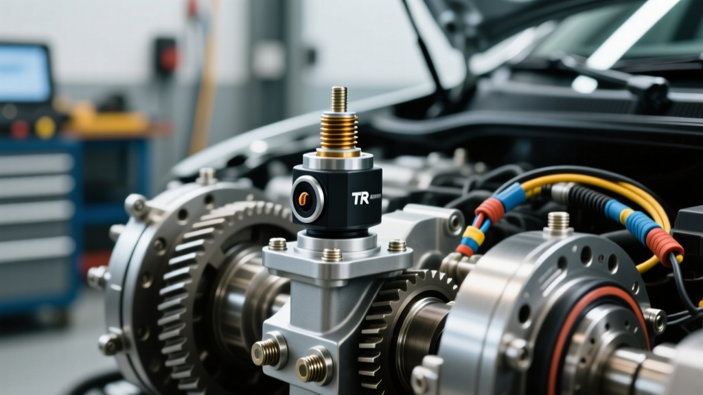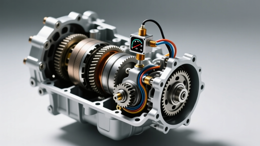
The Intersection of TRS and Speedometer Sensor Logic
When a vehicle's speedometer drops to zero while the transmission simultaneously defaults to limp mode, many technicians immediately suspect a catastrophic internal mechanical failure or a dying Transmission Control Module (TCM). However, in modern powertrain networks, this exact symptom cluster is frequently the result of a rationality conflict between the transmission range sensor TRS and the Output Speed Sensor (OSS), also known as the Vehicle Speed Sensor (VSS). While these two components serve entirely different primary functions—one identifying the driver's gear selection (PRNDL) and the other measuring the rotational speed of the transmission output shaft—the TCM relies on a continuous cross-check between them to validate powertrain operation.
In this technical deep-dive, we will explore why the TCM links the transmission range sensor TRS and speedometer sensor data, how shared 5-volt reference circuits can take down both systems simultaneously, and the exact oscilloscope and multimeter procedures required to isolate the fault on popular platforms like the Ford 6R80 and GM 4L60E/6L80.
Why the TCM Cross-References Gear Range and Vehicle Speed
The TCM is programmed with a strict rationality matrix. It constantly compares the Input Speed Sensor (ISS), the Output Speed Sensor (OSS), and the transmission range sensor TRS to calculate gear ratios and detect slip. If the TCM reads a 'Drive' or 'Reverse' signal from the TRS, it expects a corresponding change in the OSS speedometer data relative to engine RPM. Conversely, if the TRS reports 'Park' or 'Neutral' but the OSS registers 45 MPH, the TCM flags a critical rationality fault.
When this conflict occurs, the TCM cannot safely determine if the transmission is experiencing massive internal clutch slip, a broken output shaft, or a catastrophic sensor failure. To protect the driveline, the TCM triggers a fail-safe limp mode. During this state, the TCM may intentionally disable the CAN-bus broadcast for vehicle speed, causing the instrument cluster speedometer to drop to zero, while simultaneously setting codes like P0705 (TRS Circuit Malfunction) alongside P0500 (VSS Circuit) or P0720 (OSS Circuit). According to OBD-II Code P0705 diagnostic guidelines, a range sensor circuit malfunction often forces the TCM to ignore all speed-based shift solenoids, locking the transmission in a single default gear (usually 3rd or 4th).
Shared Circuit Vulnerabilities: The 5V Reference and Ground Networks
Before replacing sensors, it is vital to understand that the transmission range sensor TRS and the speedometer sensor (OSS/VSS) often share the same low-voltage reference and ground circuits originating from the TCM. In the widely used Ford 6R80 and GM 6L80 transmissions, the main internal and external wiring harnesses route through tight spaces near the bellhousing and transmission pan.
- Chafing and Shorts: The harness routing from the side-mounted TRS to the rear-extension-mounted OSS is notorious for rubbing against the transmission case or bellhousing bolts. A short to ground on the shared 5V reference wire will instantly collapse the voltage supply to both sensors.
- Corrosion at the TCM Connector: Water intrusion at the main TCM bulkhead connector (common in vehicles where the TCM is mounted near the radiator or in the wheel well) causes galvanic corrosion across adjacent pins. Because the TRS signal pins and OSS signal pins are often grouped together in the connector harness, a single corroded pin bridge can cross-talk the signals, confusing the TCM.
- Fluid Contamination: On transmissions where the TRS is internal (like the GM 6L80 Internal Mode Switch), degraded transmission fluid containing high metallic particulate counts can cause the sensor's contact wipers to short out, dragging down the shared sensor ground plane and corrupting the Hall-effect signal of the OSS.
Diagnostic Matrix: TRS vs. OSS/VSS Faults
Use the following matrix to differentiate between isolated sensor failures and shared network faults. This framework helps prevent the unnecessary replacement of expensive components.
| Symptom / Code | TRS Status | Speedometer / OSS Status | Probable Root Cause |
|---|---|---|---|
| P0705 Only | Fails to read PRNDL | Operates Normally | Isolated TRS adjustment, worn wiper contacts, or TRS-specific signal wire break. |
| P0720 / P0500 Only | Reads PRNDL Correctly | Drops to Zero / Erratic | Failed OSS Hall-effect element, damaged reluctor ring on output shaft, or OSS wiring break. |
| P0705 + P0720 + Limp Mode | Invalid / Default | Drops to Zero | Shared 5V Reference short, common sensor ground open, or TCM bulkhead connector corrosion. |
| P0730 (Gear Ratio Error) | Reads Correct Gear | Erratic / Low Voltage | Intermittent OSS signal loss causing TCM to miscalculate slip; speedometer may flutter. |
Pro Tip: If you pull the key out and the speedometer needle does not drop to zero immediately, or if the digital cluster displays dashes, the TCM has actively suspended the CAN-bus vehicle speed message due to a rationality conflict between the TRS and OSS data.
Oscilloscope and Multimeter Testing Procedures
To properly diagnose linked transmission range sensor TRS and speedometer sensor issues, you must move beyond basic OBD-II scanners and utilize a digital storage oscilloscope (DSO) and a high-impedance multimeter. As detailed in SAE International technical papers on powertrain diagnostics, analyzing the waveform is the only definitive way to prove circuit integrity under load.
Testing the Output Speed Sensor (Speedometer Data)
Most modern OSS/VSS units are Hall-effect sensors. They require three wires: a 5V to 12V power supply, a dedicated ground, and a square-wave signal return.
- Backprobe the Signal Wire: Connect your DSO to the OSS signal wire at the TCM connector or sensor pigtail.
- Raise the Drive Wheels: Safely lift the vehicle and spin the drive wheels by hand or run the vehicle on a lift.
- Analyze the Waveform: You should see a crisp, clean square wave toggling between 0V and 5V (or 12V, depending on the OEM). The frequency will increase as wheel speed increases. If the waveform shows rounded edges, voltage drops below 4V on the high side, or random dropouts, you have a wiring resistance issue or a failing Hall-effect chip. A variable reluctance (VR) sensor, found on older GM 4L60E applications, will output an AC sine wave that grows in amplitude and frequency with speed.
Testing the Transmission Range Sensor TRS
The TRS is typically a series of resistors or mechanical switches arranged in a voltage divider network. The TCM sends a 5V reference and reads the return voltage to determine the shift lever position.
- Voltage Drop Test: Backprobe the TRS signal wire. With the key on, engine off, move the shifter through all detents. You should see distinct, stepped voltage changes (e.g., Park = 4.2V, Reverse = 3.1V, Neutral = 2.4V, Drive = 1.5V).
- Resistance Check: If the voltages are erratic or floating, disconnect the sensor and measure resistance across the sensor pins. Compare your findings to the OEM specification chart. For instance, if the 'Drive' circuit shows infinite resistance or fluctuates wildly when you tap the sensor housing, the internal copper wipers are worn, necessitating replacement.
Component Replacement: Torque Specs and Part Numbers
When the diagnostic data confirms a hard component failure, precision during reassembly is critical. Overtightening sensor mounting bolts can warp the sensor housing or crack the transmission case, leading to fluid leaks and misalignment with the reluctor rings. Below are specific replacement parameters for two of the most common platforms experiencing these linked failures.
Ford 6R80 (F-150, Mustang)
- TRS Part Number: Motorcraft SW-7189 (Approx. $45 - $65). The TRS is mounted externally on the side of the transmission case, linked to the manual lever.
- OSS Part Number: Motorcraft DY-1266 (Approx. $30 - $45). Located on the rear extension housing.
- TRS Mounting Torque: 10 Nm (89 lb-in). Ensure the manual lever is precisely aligned with the neutral detent mark on the case before tightening.
- OSS Mounting Torque: 11 Nm (97 lb-in). Inspect the O-ring and apply a light coat of clean ATF before insertion to prevent binding.
GM 4L60E / 4L80E (Silverado, Tahoe)
- TRS (Neutral Safety Switch) Part Number: ACDelco 213-4644 (Approx. $35 - $50).
- VSS Part Number: ACDelco 213-4644 (Note: VSS and TRS part numbers vary by exact year; always verify via VIN. A common VSS is ACDelco 213-384, approx. $25).
- TRS Torque: 12 Nm (106 lb-in). Alignment requires a specialized pin or drill bit inserted through the alignment hole while in Neutral.
- VSS Bolt Torque: 15 Nm (11 lb-ft). Ensure the hold-down bracket is not bent, as this alters the air gap between the sensor and the reluctor ring.
For further diagnostic code breakdowns, including the exact freeze-frame parameters to look for when the TCM sets a rationality fault, technicians can reference the OBD-II Code P0720 Output Speed Sensor Circuit database. By understanding the deep logical links between the transmission range sensor TRS and the speedometer sensor data, you can accurately diagnose complex electrical gremlins, avoid unnecessary transmission teardowns, and restore proper TCM operation on the first attempt.