The Physics of Powertrain Restraint
Every internal combustion and hybrid electric vehicle generates massive rotational and longitudinal forces that must be managed before they reach the wheels. While motor and transmission mounts handle static weight and high-frequency vibrations, the drivetrain stabilizer is specifically engineered to limit powertrain excursion under heavy torque loads. In 2026, as average engine torque outputs continue to climb across all segments, the failure rate of neglected stabilizer components has become a primary source of driveline NVH (Noise, Vibration, and Harshness) complaints.
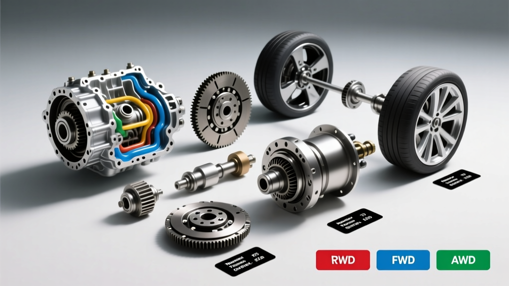
However, the architecture, failure modes, and repair protocols for a drivetrain stabilizer vary wildly depending on whether the vehicle utilizes a Front-Wheel Drive (FWD), Rear-Wheel Drive (RWD), or All-Wheel Drive (AWD) layout. This model-specific repair guide breaks down the exact engineering differences, OEM part numbers, and torque specifications required to service these critical components across three iconic platforms.
FWD Architecture: Managing Transverse Torque Roll
In a transverse FWD layout, the engine and transmission are mounted side-by-side. When the drive wheels apply torque to the pavement, the entire powertrain assembly attempts to rotate on its horizontal axis—a phenomenon known as torque roll. The primary drivetrain stabilizer in this configuration is the upper torque strut, commonly referred to as a 'dog bone' mount.
Model Focus: Honda Accord 2.0T (10-Speed Automatic)
The 10-speed automatic (10AT) in the modern Honda Accord generates substantial low-end torque. If the upper torque strut fails, the transmission casing physically shifts during aggressive 1st-to-2nd gear shifts, causing a harsh metallic clunk and premature wear on the CV axles.
- OEM Part Number: 50820-TBA-A01 (Upper Torque Strut Assembly)
- Hardware: M12x1.25 flange bolts
- Torque Specification: 64 Nm (47 lb-ft) followed by an additional 90-degree turn (torque-to-yield)
- Average Part Cost: $45 - $75 via RockAuto
Repair Insight: When replacing the FWD drivetrain stabilizer, the vehicle must be resting on its wheels (or on a drive-on lift) to keep the suspension and engine at normal ride height. Torquing the M12 bolts while the engine is hanging at full droop will pre-load the elastomeric bushing, leading to a torn stabilizer within 5,000 miles.
RWD Architecture: Longitudinal Thrust and Driveline Dampening
Rear-wheel drive platforms mount the powertrain longitudinally. Instead of torque roll, the primary force is longitudinal thrust—the entire drivetrain attempts to push backward into the firewall under acceleration. In modern RWD vehicles, the drivetrain stabilizer system is distributed between the transmission crossmember mounts and the flex disc (guibo) connecting the transmission output shaft to the driveshaft.
Model Focus: BMW G20 330i (ZF 8HP50 Transmission)
The BMW G20 chassis relies on the ZF 8HP50 8-speed automatic. The flex disc acts as a rotational drivetrain stabilizer, absorbing torsional spikes from the torque converter, while the integrated ZF transmission side mounts handle lateral and vertical stabilization.
- OEM Part Number (Flex Disc): 26117527475 (Febi or OEM Lemförder)
- OEM Part Number (ZF Side Mount): 22316799331
- Hardware: M10x1 hex bolts with self-locking nuts
- Torque Specification (Flex Disc): 65 Nm (48 lb-ft) + 90 degrees
- Fluid Note: If the ZF 8HP mechatronic sleeve or pan is disturbed during crossmember stabilization work, a dry-fill capacity of 9.5L of ZF LifeguardFluid 8 is required. Refer to ZF Group technical bulletins for the exact 40°C-50°C leveling procedure.
Repair Insight: The BMW flex disc features a centering sleeve that must align perfectly with the transmission output shaft pilot bearing. Forcing the driveshaft into a degraded stabilizer disc will cause immediate high-speed driveline shudder (typically felt between 55-65 mph) and will destroy the ZF 8HP output shaft seal.
AWD Architecture: Multi-Axis Pitch and Yaw Control
All-wheel drive systems must manage transverse torque roll, longitudinal thrust, and the torsional feedback from the rear differential. Symmetrical AWD layouts require a multi-point stabilization network, heavily relying on the pitch stop mount and rear differential stabilizer bushings.
Model Focus: Subaru Outback 2.5i (Lineartronic CVT)
Subaru’s Symmetrical AWD system uses a pitch stop mount located between the engine block and the firewall. This specific drivetrain stabilizer prevents the boxer engine and CVT assembly from pitching forward and backward during hard braking and initial CVT belt-grab acceleration.
- OEM Part Number: 41022AJ000 (Pitch Stop Mount)
- Hardware: M10x1.25 flange bolts
- Torque Specification: 63 Nm (46.5 lb-ft)
- Average Part Cost: $35 - $60
Repair Insight: Subaru's pitch stop is notorious for tearing the internal rubber voids. According to SAE International NVH studies, a degraded AWD pitch stop allows low-frequency booming (30-50 Hz) to transfer directly into the cabin firewall. Always inspect the rear differential 'mustache' bushings concurrently; if the pitch stop is torn, the rear diff stabilizer bushings are likely compromised from taking the excess driveline lash.
Comparative Data Matrix: Drivetrain Stabilizer Configurations
| Drivetrain Layout | Primary Stabilizer Component | Typical Failure Symptom | OEM Part Example | Avg. Dealer Repair Cost |
|---|---|---|---|---|
| FWD (Transverse) | Upper Torque Strut (Dog Bone) | Clunk on P-to-R engagement; wheel hop | Honda 50820-TBA-A01 | $180 - $240 |
| RWD (Longitudinal) | Flex Disc (Guibo) & Trans Mounts | 55-65 mph vibration; harsh downshifts | BMW 26117527475 | $450 - $650 |
| AWD (Symmetrical) | Pitch Stop & Rear Diff Bushings | Firewall booming; CVT engagement lag | Subaru 41022AJ000 | $220 - $310 |
Advanced Diagnostic Protocols for Stabilizer Failure
Visual inspection of the exterior rubber is rarely sufficient for diagnosing a failing drivetrain stabilizer, as modern hydraulic and voided bushings often fail internally while maintaining a pristine exterior appearance. Utilize these professional diagnostic frameworks:
1. The Brake-Torque Load Test
With the vehicle secured on a lift (wheels free to spin but restrained by a safety strap or assistant), start the engine and firmly apply the brake pedal. Shift between Drive and Reverse. Use a high-lumen inspection light to observe the stabilizer bushing. If the inner metal sleeve moves more than 4mm relative to the outer bracket, the elastomeric matrix has suffered shear failure.
2. The Pry-Bar Leverage Method
For RWD and AWD setups where the drivetrain stabilizer is located beneath the vehicle (e.g., transmission crossmember mounts or rear differential bushings), use a 24-inch pry bar placed against a solid chassis point. Apply moderate upward pressure to the transmission pan or differential housing. Healthy stabilizer bushings will resist movement and snap back immediately. Degraded bushings will exhibit 'dead-band' movement—a noticeable delay or free-play before the rubber engages.
3. NVH Frequency Analysis
Modern diagnostic tools utilize smartphone-based accelerometers to map cabin vibrations. A failing FWD torque strut typically manifests as a high-amplitude spike at engine idle RPM frequencies (25-35 Hz). Conversely, a failing RWD flex disc or AWD rear diff stabilizer will trigger a harmonic resonance spike corresponding to driveshaft rotational speed, usually isolated between 1200-1800 RPM under light throttle cruising.
Final Torque and Alignment Considerations
Regardless of whether you are servicing a Honda, BMW, or Subaru, the golden rule of drivetrain stabilizer repair is loaded-torqueing. Never fully torque a stabilizer fastener while the drivetrain is hanging on a hoist. The vehicle's weight must be resting on the suspension to ensure the bushing is centered in its neutral resting position. Failing to follow this protocol will introduce a permanent torsional preload, guaranteeing a premature failure and a costly comeback to the service bay.