The Modern Diagnostic Dilemma: Mechanical Levels vs. Electronic Pressures
One of the most common frustrations in modern drivetrain diagnostics is the 'phantom slip.' You pull the dipstick, verify the fluid is at the correct level, and confirm the color is a healthy, translucent red. Yet, the vehicle still triggers a check engine light, enters limp mode, or flares during the 2-3 upshift. In the era of electronically controlled automatics, knowing how to read automatic transmission fluid dipstick markings is only ten percent of the battle. The other ninety percent relies on understanding transmission fluid pressure sensor issues and interpreting live hydraulic data.
This 2026 buyer’s guide and diagnostic comparison bridges the gap between old-school mechanical fluid checks and modern electronic pressure verification. Whether you are driving a GM 6L80, a Ford 6R80, or a ZF 8HP-equipped vehicle, we will compare OEM versus aftermarket pressure sensors, evaluate the scan tools required to read them, and outline the exact diagnostic framework to separate a simple fluid level error from a catastrophic valve body failure.
How to Read Automatic Transmission Fluid Dipstick Correctly
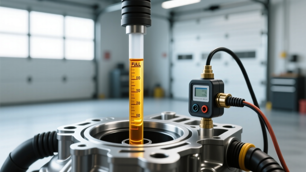
Before condemning a pressure sensor, you must eliminate mechanical fluid volume issues. Reading a transmission dipstick is highly temperature-dependent, and guessing the fluid level is a primary cause of misdiagnosed pressure faults.
- GM 6L80 / 8L90: Requires a specific temperature window. The 'COLD' band is only valid if the fluid is between 86°F and 122°F (30°C–50°C). For the 'HOT' band, the transmission fluid temperature (TFT) must be between 160°F and 200°F (71°C–93°C). The engine must be running, and the vehicle must be in Park on a level surface.
- Ford 6R80 / 10R80: Fluid must be at normal operating temperature (180°F–200°F). The vehicle must be running, with the transmission cycled through all gears before settling in Park. Ford dipsticks feature a cross-hatched zone; the fluid should be in the upper half of this zone when hot.
- ZF 8HP (Dipstick-less models): Many modern ZF applications lack a traditional dipstick, relying instead on a leveling plug on the transmission pan. Fluid level is verified when the sump temperature is exactly 86°F to 104°F (30°C–40°C) with the engine idling. If your ZF has an aftermarket or OEM auxiliary dipstick tube, the fluid must crest the lower notch at operating temp.
Expert Warning: Never trust a cold dipstick reading on a modern 8-speed or 10-speed transmission. Automatic transmission fluid (ATF) expands significantly with heat. A fluid level that reads 'full' when cold will expand and aerate when hot, causing the pump to suck air. This aeration creates erratic line pressure that perfectly mimics a failing pressure sensor.
Why Full Fluid Doesn't Prevent Limp Mode: Pressure Sensor Failures
If you know how to read automatic transmission fluid dipstick levels correctly and have confirmed the fluid is full, the next suspect is the Transmission Fluid Pressure (TFP) sensor. The TFP sensor is a piezoelectric or strain-gauge device that converts hydraulic line pressure into a voltage signal (typically 0.5V to 4.5V) for the Transmission Control Module (TCM).
When a TFP sensor fails, the TCM loses visibility into the actual hydraulic clamping force. To protect the clutches from burning up, the TCM defaults to maximum line pressure (often causing harsh, neck-snapping shifts) or triggers a limp-in mode, locking the transmission in a single gear. Common OBD-II codes include P0875 (Transmission Fluid Pressure Sensor/Switch 'D' Circuit) or P0878 (Pressure Sensor Circuit High).
2026 Buyer's Guide: OEM vs. Aftermarket Pressure Sensors
When replacing pressure sensors, the market is flooded with cheap, white-box alternatives that fail within 5,000 miles due to poor internal potting and ATF degradation. Below is a comparison of the most common replacement components for popular transmissions, comparing OEM, premium aftermarket, and budget options.
| Transmission | Component Type | OEM / Premium Part # | Est. Price (2026) | Torque Spec | Verdict |
|---|---|---|---|---|---|
| GM 6L80 / 6L90 | TEHCM (Integrated Pressure Switches) | ACDelco 24258477 | $280 - $340 | 10 Nm (89 lb-in) | Mandatory OEM. Aftermarket TEHCMs suffer from high solenoid failure rates. |
| Ford 6R80 | Output/Turbine & Pressure Sensor | Motorcraft SW-6357 | $45 - $65 | 12 Nm (106 lb-in) | OEM recommended. Standard Motor Products (SMP) is a viable backup. |
| ZF 8HP (Gen 1/2) | Mechatronic Pressure Sensor | ZF 1078.317.075 (Repair Kit) | $450 - $600 | N/A (Press-fit / Sealed) | Requires specialized soldering or full Mechatronic replacement. Avoid cheap kits. |
| Toyota A760E | Secondary Pressure Sensor | Aisin SPT-008 | $85 - $110 | 15 Nm (11 lb-ft) | Aisin is the OEM supplier. Excellent reliability and direct fitment. |
Tool Comparison: Verifying Pressure Without Dropping the Pan
You cannot diagnose transmission fluid pressure sensor issues with a $20 code reader. You need a bi-directional scan tool capable of reading live Transmission Control Module (TCM) PIDs (Parameter IDs). Specifically, you must compare Commanded Line Pressure against Actual Line Pressure while driving.
Top Scan Tools for Live Pressure Data (2026 Comparison)
- Autel MaxiCOM MK808S (Approx. $450): The best entry-level professional tool. It reads live TFP sensor voltages and PSI on GM and Ford applications reliably. However, it lacks the advanced graphing overlay needed to spot micro-second pressure drops during ZF 8HP shifts.
- Topdon Phoenix Lite 2 (Approx. $899): Offers excellent bi-directional controls and PID graphing. You can overlay 'Engine RPM', 'Commanded Pressure', and 'Actual Pressure' on a single graph. If the actual pressure deviates by more than 15 PSI from the commanded pressure under load, you have a hydraulic leak or a failing sensor.
- Snap-on Zeus+ (Approx. $6,500+): The dealership standard. Includes built-in oscilloscope functions to test the 5V reference and signal return wires of the TFP sensor simultaneously, eliminating the need to drop the transmission pan to test the sensor harness.
Step-by-Step Diagnostic Framework: Sensor vs. Mechanical Fault
Before purchasing a replacement sensor from RockAuto or your local dealer, perform this 3-step verification framework to ensure you aren't chasing a ghost.
Step 1: The Dipstick and Temperature Verification
Connect your scan tool and monitor the Transmission Fluid Temperature (TFT) PID. Drive the vehicle until the TFT reaches at least 160°F. Stop on level ground, leave the engine running, and check the dipstick. If the fluid is low, top it off with the exact OEM specification (e.g., Dexron ULV for GM 8-speeds, Mercon ULV for Ford 10-speeds). Never mix fluid specifications, as friction modifiers directly alter hydraulic pressure dynamics.
Step 2: The Voltage Drop Test
Most TFP sensors operate on a 3-wire circuit: a 5-Volt Reference, a Signal Return, and a Low Reference (Ground). Using a digital multimeter (DMM), back-probe the sensor connector (if accessible externally, such as on the Ford 6R80 case connector).
With the key on, engine off (KOEO), you should read exactly 4.8V to 5.0V on the reference wire. If you read 0V, you have a broken wire between the TCM and the sensor, or the TCM itself has failed. If the reference voltage is present, start the engine and monitor the signal wire. A healthy sensor will show a baseline voltage of roughly 0.5V to 0.8V at idle, climbing smoothly to 3.5V+ as line pressure increases under stall conditions.
Step 3: Differentiating Sensor Faults from Pump Wear
As noted by industry experts at Sonnax Technical Resources, a failing pressure sensor will often throw a rationality code (e.g., the sensor reads 0 PSI while the TCM is commanding 150 PSI). However, if the scan tool shows that Actual Pressure is genuinely low and matches the mechanical reality (resulting in slip), the sensor is likely telling the truth. The fault lies in a worn transmission pump, a stuck pressure regulator valve, or a leaking clutch apply piston. In these cases, replacing the sensor will not fix the issue; the valve body or pump requires teardown and refurbishment.
Final Thoughts on Drivetrain Diagnostics
Mastering how to read automatic transmission fluid dipstick markings is the foundational first step in any transmission diagnostic tree. But in 2026, mechanical verification must be immediately followed by electronic validation. By investing in quality OEM sensors—like ACDelco TEHCMs or Motorcraft pressure switches—and utilizing a bi-directional scan tool to graph commanded versus actual line pressure, you can accurately isolate transmission fluid pressure sensor issues before committing to an unnecessary and expensive transmission rebuild. For further reading on valve body wear and pressure regulator circuits, consult the technical archives at Transmission Digest.