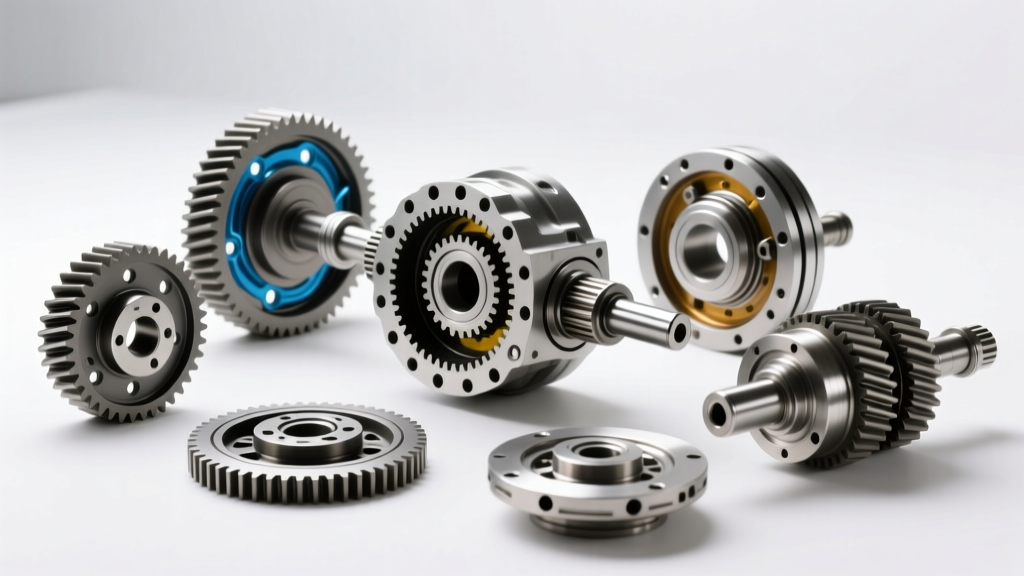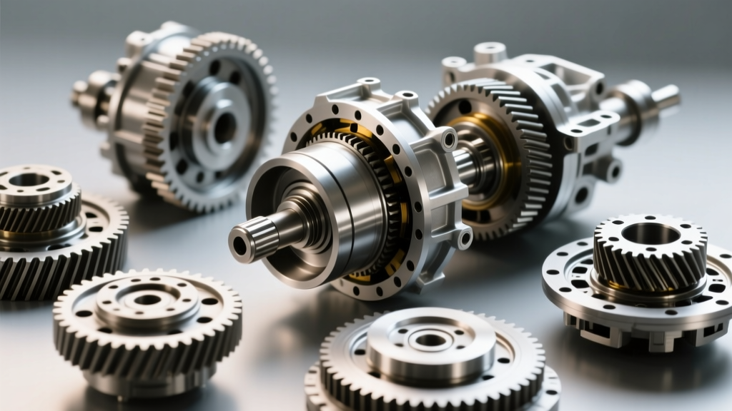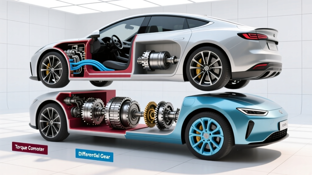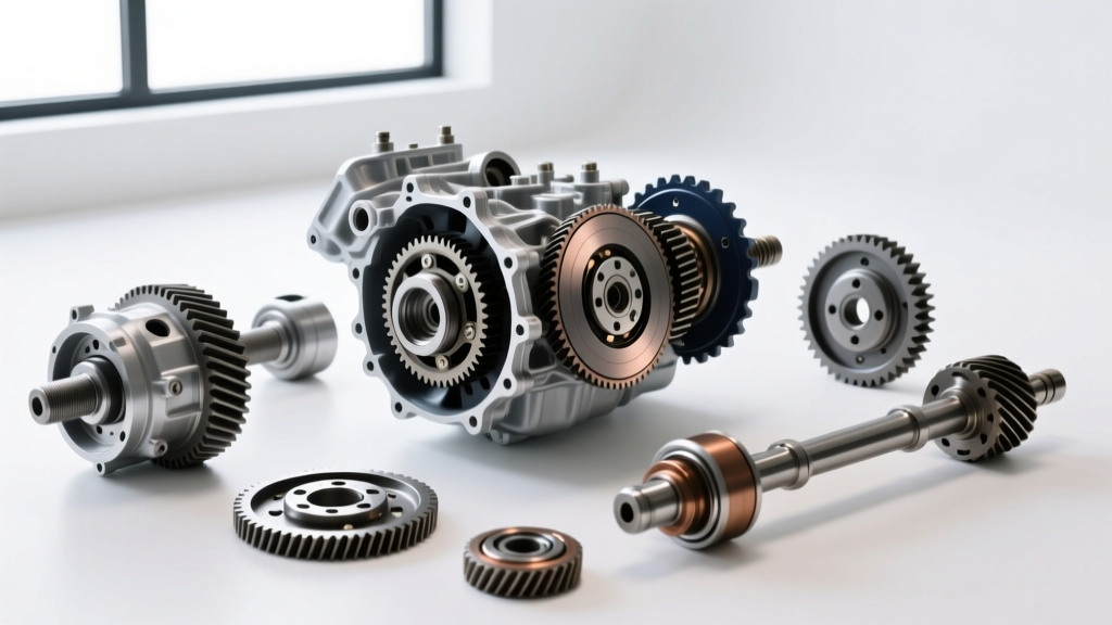
While calculus students memorize the mathematical definition of differentiability to determine if a function has a continuous derivative, automotive engineers and drivetrain specialists rely on a mechanical equivalent every single day. In the automotive world, 'differentiability' refers to the ability of a drivetrain to allow opposing drive wheels to rotate at different speeds while cornering, all while maintaining continuous torque delivery. Understanding this mechanical definition of differentiability is the cornerstone of mastering transmission and drivetrain terminology.
Whether you are rebuilding a classic GM 8.5-inch 10-bolt, servicing a Ford 8.8-inch rear end, or diagnosing a modern ZF 8HP integrated final drive, grasping the terminology and physics of the differential is non-negotiable. This step-by-step guide will walk you through essential drivetrain terminology, power flow, and the precise service specifications required to rebuild and maintain these critical components.
Step 1: Decoding Core Drivetrain Terminology
Before turning a single wrench, you must speak the language of the drivetrain. Misinterpreting terms like 'backlash' or 'preload' can lead to catastrophic gear failure within the first hundred miles. Below is a breakdown of the foundational terminology used by master technicians.
| Term | Technical Definition | Real-World Application & Specs |
|---|---|---|
| Backlash | The amount of free rotational play between the ring gear and the pinion gear teeth. | GM 10-bolt target: 0.006' - 0.010'. Measured via dial indicator at the ring gear edge. |
| Pinion Preload | The rotational resistance of the pinion bearings, ensuring the pinion gear does not deflect under heavy torque loads. | Ford 8.8-inch target: 15-25 in-lbs of rotational drag (not to be confused with nut torque). |
| Gear Contact Pattern | The physical imprint left on the ring gear teeth by the pinion gear under load, verified using yellow marking compound. | Ideal pattern is centered on the tooth face; toe-to-heel bias indicates incorrect pinion depth shimming. |
| Side Gear / Spider Gear | The internal bevel gears that allow the left and right axles to differentiate speed during cornering. | Upgrading to forged 4-pinion spider gears (e.g., Eaton part #19584-010) prevents cross-pin shearing. |
Step 2: Tracing Torque Through the Final Drive
To truly understand the definition of differentiability in a mechanical sense, you must trace the power flow from the transmission output shaft to the pavement. The transmission's output shaft delivers rotational force into the differential's pinion gear. The pinion gear meshes with the much larger ring gear, providing the final gear reduction (e.g., a 3.73:1 ratio) and multiplying torque.
The ring gear is bolted to the differential case. As the case spins, it carries the spider gears (mounted on a cross-pin) along with it. When the vehicle is traveling in a straight line, the spider gears do not rotate on their own axes; they simply push both side gears equally, locking the axles together in speed. However, when the vehicle enters a corner, the inside wheel must travel a shorter distance than the outside wheel. This resistance causes the spider gears to spin on their cross-pin, 'differentiating' the speed and allowing the outside axle to spin faster while the inside axle slows down. This elegant mechanical ballet is the physical manifestation of differentiability.
Step 3: Selecting the Right Differential Architecture
Not all differentials handle torque differentiation equally. When upgrading or replacing a unit, choosing the correct architecture dictates your vehicle's traction and drivability.
- Open Differentials: The baseline design. If one wheel loses traction, 100% of the torque is routed to the path of least resistance (the spinning wheel). Ideal only for basic commuter vehicles and highway cruising.
- Clutch-Pack Limited Slip (LSD): Uses friction discs and cone clutches to bind the side gears to the case under load. Examples include the Auburn Gear Pro-Series and factory Ford Traction-Lok. Crucial Note: These require specific friction modifiers (like Ford XL-3 or GM EOS) to prevent chatter during low-speed cornering.
- Helical / Torque-Biasing (Torsen): Utilizes worm gears and helix angles to bind under load without clutch packs. The Torsen T-3 (approx. $850 - $1,100) is highly prized for its seamless, maintenance-free torque biasing. Unlike clutch-type LSDs, Torsen units do not require friction modifiers and operate perfectly on standard 75W-90 synthetic gear oil.
- Automatic Lockers (e.g., Detroit Locker): Mechanically locks both axles together, only allowing differentiation when the vehicle overruns the drivetrain during cornering. Extremely durable for off-road and drag racing, but produces noticeable clunking and understeer on paved streets.
Step 4: Executing a Precision Differential Service
Servicing a differential goes far beyond draining and filling fluid. A proper rebuild or gear swap requires meticulous measurement. According to Ring & Pinion technical guides, over 70% of premature gear whine and failure is caused by improper pinion depth and backlash settings, not manufacturing defects.
Critical Rebuild Sequence & Torque Specifications
When installing a new ring and pinion set (such as a Motive Gear Master Kit MK GM8.5-373, typically $180-$240), follow this exact sequence to ensure longevity:
- Set Pinion Depth: The distance from the pinion gear centerline to the ring gear centerline must be exact. Use a pinion depth setting tool and gear marking paste. Adjust the pinion depth shim (usually located behind the inner pinion bearing race) in 0.001-inch increments until the contact pattern is perfectly centered on the coast and drive sides of the ring gear teeth.
- Establish Pinion Bearing Preload: Install the new crush sleeve (or solid spacer kit for high-horsepower applications). Tighten the pinion nut. You must measure rotational preload using an inch-pound torque wrench. For a GM 8.5-inch 10-bolt with new bearings, you are looking for 20-30 in-lbs of rotational resistance. Warning: The actual torque required on the pinion nut to achieve this can exceed 250 ft-lbs. Never guess this measurement.
- Set Backlash: Mount a dial indicator to the differential housing, resting the stylus on a ring gear tooth. Adjust the side bearing adjuster nuts (or shims) to achieve 0.008 inches of backlash. Rotate the ring gear and check at four equidistant points; variance should not exceed 0.002 inches, which indicates a warped ring gear or improper mounting.
- Final Torque & Fluid Fill: Ring gear bolts on a Ford 8.8-inch must be torqued to 70-85 ft-lbs using red Loctite 272. Fill the housing with 2.5 to 3.0 pints of high-quality 75W-90 synthetic gear oil (e.g., Amsoil Severe Gear). If running a clutch-type LSD, add exactly 4 ounces of limited-slip friction modifier before topping off.
Mastering the Drivetrain
The mechanical definition of differentiability is what keeps your tires on the pavement and your drivetrain intact through thousands of miles of cornering and torque delivery. By mastering the terminology, understanding the internal power flow, and adhering to strict, manufacturer-level torque and measurement specifications, you transition from a parts-swapper to a true drivetrain specialist. For further engineering data on torque-biasing differentials, consult Eaton's automotive differential engineering portal or review OEM service manuals for your specific axle housing.