The Calculus Confusion: Differentiability Definition Math vs. Mechanical Reality
It is surprisingly common for automotive engineering students and DIY mechanics to cross wires between advanced calculus and drivetrain mechanics. When you look up the differentiability definition math concept, you are diving into calculus: a function is 'differentiable' if it has a derivative at every point in its domain, meaning its graph is smooth, continuous, and lacks any sharp corners or cusps. But how does this mathematical definition of 'smoothness' relate to the physical transmission basic components bolted to the back of your engine?
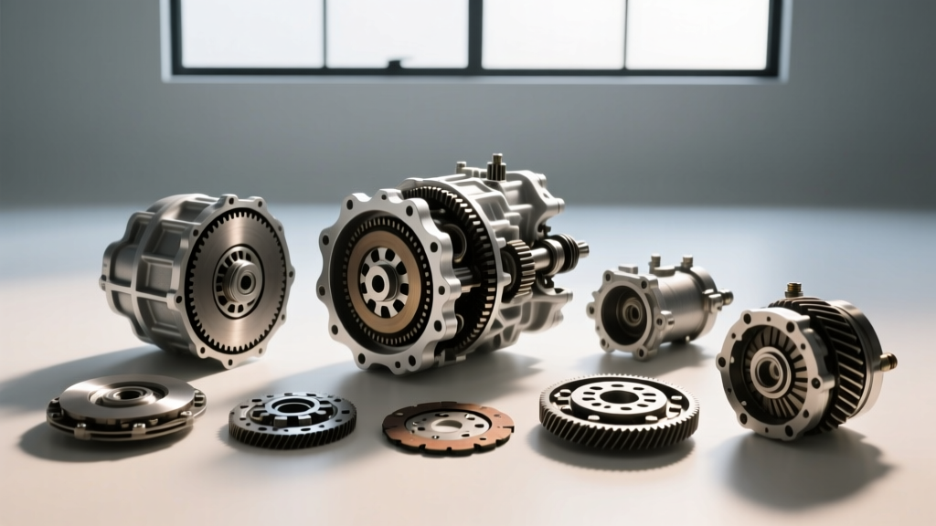
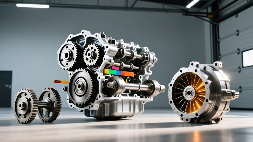
In automotive engineering, achieving mathematical 'smoothness'—the absence of harsh, abrupt torque spikes during gear shifts—is the exact goal of modern transmission design. As of 2026, with 8-speed, 9-speed, and 10-speed automatic transmissions dominating the market, engineers use complex algorithms to mimic a continuous, differentiable torque curve. They achieve this physical smoothness through a highly orchestrated network of mechanical and hydraulic components. Let us break down the anatomy of an automatic transmission, bridging the gap between theoretical math and heavy-duty mechanical reality.
Transmission Basic Components: The Anatomy of Gear Shifting
To understand how a vehicle multiplies torque and manages speed, we must look inside the transmission casing. Whether you are rebuilding a classic GM 4L60E or diagnosing a modern ZF 8HP70, the foundational architecture remains remarkably consistent.
1. The Torque Converter: Fluid Coupling and Stall
The torque converter replaces the mechanical clutch found in manual transmissions. It is a fluid coupling device that transfers rotating power from the engine to the transmission input shaft. Inside the welded steel housing, you will find three main elements: the impeller (pump), the turbine, and the stator.
- The Impeller: Driven directly by the engine's flexplate, it flings transmission fluid outward via centrifugal force.
- The Turbine: Connected to the transmission input shaft, it catches the fluid, translating hydraulic energy back into mechanical rotation.
- The Stator: Sits between the impeller and turbine on a one-way clutch, redirecting fluid flow to multiply torque (often by a factor of 2.0:1 to 2.5:1 at stall).
Modern units, like the GM 6L80 (RPO MYC) torque converter, feature a Torque Converter Clutch (TCC) with Electronic Controlled Capacity Clutch (EC3) technology. This allows the TCC to slip microscopically, absorbing engine harmonics and creating that mathematically 'smooth' torque transfer curve, eliminating the harsh lockup shudder of older generations.
2. Planetary Gearsets: The Ratio Multipliers
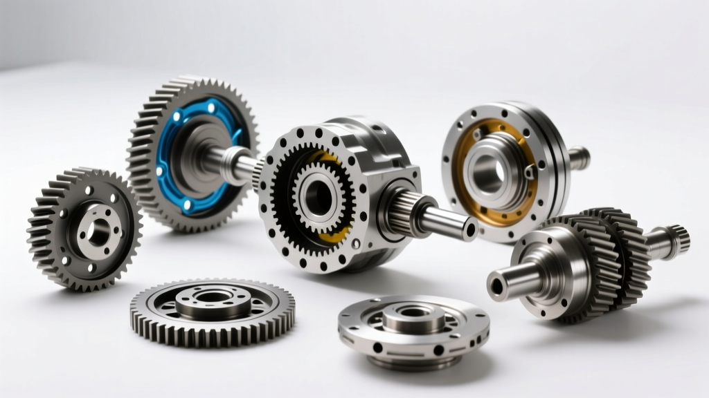
Unlike manual transmissions that use parallel shafts and sliding dog rings, automatics rely on planetary gearsets. A standard planetary set consists of a sun gear (center), planet gears (mounted on a carrier), and an outer ring gear. By holding one component stationary, driving a second, and using the third as the output, the transmission achieves different gear ratios.
Advanced transmissions use compound gearsets. The ZF 8HP series, ubiquitous in 2026 luxury and performance vehicles, utilizes a Lepelletier gearset. This design places a simple planetary gearset in front of a Ravigneaux gearset, allowing for eight forward gears using only four gearsets and five shift elements, drastically reducing rotational mass and internal drag.
3. Clutch Packs, Friction Discs, and Apply Components
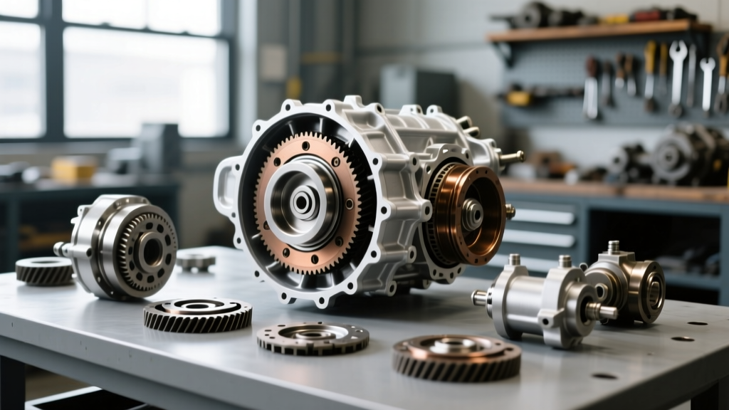
To hold or drive specific members of the planetary gearset, the transmission uses hydraulic clutch packs. A clutch pack consists of alternating steel reaction plates and friction discs lined with specialized paper, Kevlar, or carbon-based materials.
Expert Rebuild Spec: When rebuilding a Ford 6R80 or GM 8L90, clutch pack clearance is critical. The industry standard rule of thumb is 0.005 inches of clearance per friction surface. If a pack has 5 friction discs (10 surfaces), your target clearance is roughly 0.050 inches, typically adjusted by selecting a selective snap-ring or pressure plate of specific thickness. Too tight, and the clutches drag and burn; too loose, and you experience delayed, flaring shifts.
4. The Valve Body and Solenoids
The valve body is the hydraulic control center, containing a maze of channels and valves. In modern transmissions, mechanical valves are largely actuated by electronic solenoids. Pulse-Width Modulated (PWM) solenoids cycle on and off hundreds of times per second to precisely regulate line pressure to the clutch packs, ensuring shift timing is exact and shift feel is calibrated to the manufacturer's specifications.
The Mechanical Differential: Where the Math Meets the Pavement
No discussion of drivetrain components is complete without addressing the mechanical differential. While the math definition of differentiability deals with rates of change, the mechanical differential deals with rotational speed differences between the left and right drive wheels during a corner.
When a car turns, the outside wheel must travel a longer distance—and therefore spin faster—than the inside wheel. The differential assembly, typically housed in the rear axle or integrated into a transaxle, allows this speed differentiation while still applying torque to both wheels.
The Open Differential Limitation: A standard 'open' differential always sends torque to the path of least resistance. If one wheel is on ice, it will spin endlessly while the wheel with traction receives zero torque. This is why performance and off-road vehicles utilize Limited Slip Differentials (LSDs) or locking differentials.
For enthusiasts upgrading a GM 10-bolt or 12-bolt rear end, the Eaton Truetrac (e.g., Part # 910A4334 for GM 8.625" axles) is a premier choice. Unlike clutch-type LSDs that require special friction-modifier additives and wear out over time, the Truetrac uses a helical gear design to multiply torque to the wheel with traction, operating smoothly and silently without the harsh 'chatter' of traditional clutch packs.
Diagnostic Data: Component Functions, Failures, and 2026 Pricing
Understanding how these components fail is crucial for diagnostics. Below is a breakdown of common transmission basic components, their primary failure modes, and estimated replacement costs for the 2026 aftermarket and OEM landscape.
| Component | Primary Function | Common Failure Symptom | Est. Parts Cost (2026) |
|---|---|---|---|
| Torque Converter (OEM) | Fluid coupling & torque multiplication | Shudder at 40-50 mph, TCC slip codes (P0741) | $350 - $800 |
| Mechatronic / Valve Body | Hydraulic routing & electronic control | Harsh engagements, limp mode, solenoid codes | $600 - $1,400 |
| Clutch Pack Module | Locks planetary gearset members | Flaring shifts, RPM spikes between gears | $150 - $300 (per pack) |
| Helical LSD (e.g., Eaton) | Biases torque across the axle | One-wheel spin, clunking on deceleration | $650 - $950 |
Precision Assembly: Torque Specs and Fluid Capacities
Whether you are performing a fluid service or a full teardown, adhering to exact specifications is what separates a reliable build from a catastrophic failure. Here are real-world specifications for two of the most common transmissions on the road:
- GM 6L80 / 6L90:
- Fluid Type: Dexron VI (Do not mix with older Dexron III).
- Dry Fill Capacity: ~11.2 Liters (Pan removal service usually takes 5-6 Liters).
- Pan Bolt Torque: 10 Nm (89 lb-in). Warning: These are small M6 bolts; over-torquing will snap them or strip the aluminum casing.
- ZF 8HP70 / 8HP75:
- Fluid Type: ZF LifeguardFluid 8 (Often sold as Mopar 8&9 Speed ATF or Shell 134.24).
- Dry Fill Capacity: ~9.0 to 10.0 Liters depending on the specific pan/cooler setup.
- Measuring Temperature: Fluid level must be checked with the transmission fluid temperature exactly between 30°C and 50°C (86°F - 122°F) via a bi-directional scan tool, with the engine idling in Park.
Summary
While the differentiability definition math concept belongs strictly to the realm of calculus and continuous functions, the pursuit of 'smoothness' is the driving force behind modern transmission engineering. From the fluid dynamics of the torque converter to the precise clearances of Kevlar-lined clutch packs and the torque-biasing gears of a mechanical differential, every component is designed to deliver seamless, continuous power to the pavement. By understanding these transmission basic components, their exact specifications, and their failure modes, you can confidently diagnose, maintain, and upgrade your vehicle's drivetrain for years of reliable service.
For further reading on drivetrain mechanics and historical transmission evolution, consult resources like the HowStuffWorks Automatic Transmission Guide or technical bulletins via Transmission Digest.