The Physics of Engagement: How a Clutch Plate Works Under Load
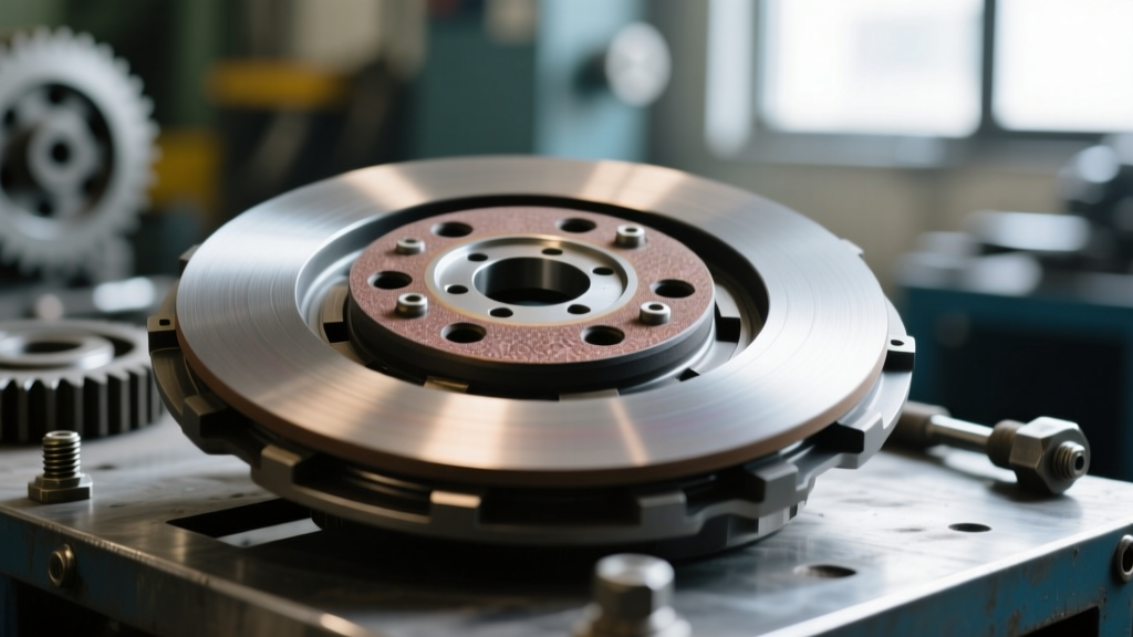
To accurately diagnose driveline NVH (Noise, Vibration, and Harshness) and slip conditions, a technician must first understand how a clutch plate works at the metallurgical level. The clutch disc acts as the sacrificial friction interface between the engine's rotating assembly (flywheel) and the transmission input shaft. When the pressure plate clamps the disc against the flywheel, kinetic energy is transferred via friction. The torque capacity of this assembly is dictated by the clamp load (lbs), the effective radius of the friction surface, and the coefficient of friction (μ) of the disc material.
In 2026, with modern powertrains pushing well past 600 lb-ft of torque in street applications (such as supercharged GM LT4 or Ford Predator platforms), selecting and diagnosing the correct friction material is critical. Misdiagnosing a material-specific failure mode often leads to unnecessary transmission teardowns. Below, we break down the symptom diagnosis and troubleshooting protocols for the three primary clutch disc materials: organic, ceramic, and sintered iron.
Organic Friction Materials: Daily Driving & Glazing Diagnostics
Organic clutch discs are composed of a composite matrix of fiberglass, Kevlar, carbon, and metallic powders bound together with phenolic resins. They offer a high-friction coefficient at low temperatures (μ = 0.30 to 0.38) and provide the smooth, progressive engagement required for daily driving and luxury sport applications.
Common Failure Modes & Symptoms
- High-Speed Slip: If an organic disc slips at high RPM but holds at low RPM, the resin binder is likely thermally degrading. Organic facings begin to outgas and lose friction above 400°F (204°C).
- Glazing: Characterized by a shiny, hardened surface on the friction material. This occurs from excessive 'riding' of the clutch pedal or chronic low-speed slipping in stop-and-go traffic.
- Contamination Slippage: Organic materials are highly porous. A weeping rear main seal or transmission input shaft seal will wick oil into the disc, destroying the friction coefficient instantly.
Troubleshooting Protocol
When diagnosing a slipping organic clutch, first verify hydraulic system integrity. A restricted compensation port in the master cylinder can prevent the clutch from fully engaging, mimicking a worn disc. Next, inspect the flywheel friction surface. If the organic disc has glazed, the flywheel will exhibit heat checking (micro-cracks) or bluing. According to RAM Clutches Tech, a glazed organic disc cannot be sanded and reused; the resin matrix is permanently altered, and replacement of both the disc and flywheel (or resurfacing to OEM thickness specs) is mandatory.
Ceramic Compounds: High-Mu Chatter & Runout Sensitivity
Ceramic clutch discs utilize sintered ceramic and metallic compounds designed to withstand extreme thermal loads. They operate with a higher coefficient of friction (μ = 0.40 to 0.48) and can survive thermal spikes up to 800°F (426°C). These are common in forced-induction street builds and dedicated track cars utilizing transmissions like the Tremec T56 Magnum XL.
Common Failure Modes & Symptoms
- Low-Speed Chatter: The most frequent complaint with ceramic discs. Because ceramic lacks the low-temperature compliance of organic resins, it tends to 'grab' rather than slip progressively when cold.
- Aggressive Engagement Shock: Can lead to premature wear on transmission input shaft splines or driveline U-joints if the driver is not accustomed to the narrow engagement window.
- Flywheel Scoring: Ceramic materials are highly abrasive. If the clutch is slipped excessively, the ceramic facing will machine grooves into a standard cast-iron flywheel.
Troubleshooting Protocol
Chatter in a ceramic clutch is often misdiagnosed as a warped pressure plate. In reality, 80% of ceramic chatter issues stem from excessive flywheel runout or improper bedding. Ceramic discs require a precise heat-cycling bedding process to transfer a uniform layer of friction material to the flywheel. If a customer reports chatter on a newly installed ceramic kit, measure the flywheel runout using a dial indicator. Runout must not exceed 0.003 inches. Furthermore, inspect the engine and transmission mounts; the aggressive engagement of ceramic materials will amplify NVH if the polyurethane or hydraulic mounts are degraded.
Sintered Iron: Drag Racing, Heat Cycling & Puck Wear
Sintered iron (often seen in 2-to-4 puck configurations) is the material of choice for drag racing and high-horsepower competition vehicles. Manufactured by fusing iron and copper powders under extreme heat and pressure, sintered discs boast a massive μ of 0.50 to 0.60 and can withstand temperatures exceeding 1,000°F (538°C) without fading.
Common Failure Modes & Symptoms
- Cold Slippage: Sintered iron requires high operating temperatures to achieve its peak friction coefficient. A sintered clutch will often slip during low-load, cold driving conditions.
- Puck Shearing: Under extreme shock loads (e.g., dumping the clutch on a trans-brake release), the sintered pucks can physically shear off the hub plate if the torsional dampers are inadequate.
- Flywheel Welding: In extreme over-temperature events, sintered iron can literally weld itself to a steel flywheel, rendering the pedal completely stuck to the floor.
Troubleshooting Protocol
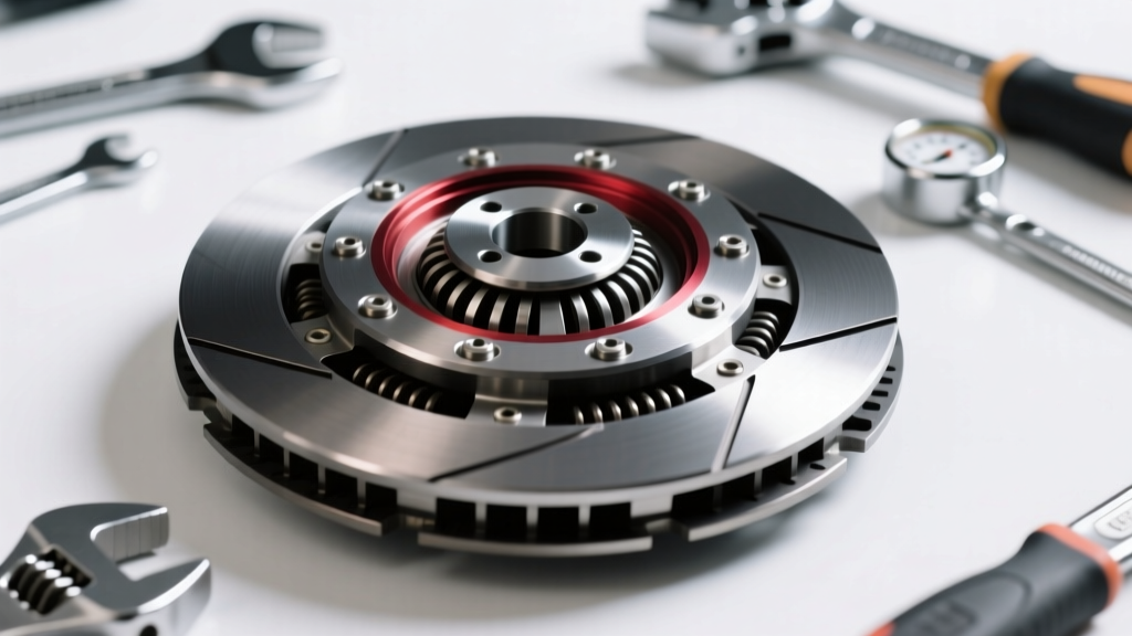
Diagnosing a sintered clutch requires looking at the hub assembly. Because sintered pucks offer zero driveline dampening on their own, the hub must contain heavy-duty torsional springs or elastomeric dampers. If you hear a metallic clunk upon engine shut-off or during gear changes, the hub springs have likely collapsed or broken. Consult the McLeod Racing Technical Resources for specific hub inspection criteria, as a failed hub will destroy the transmission input shaft bearings due to unmitigated torsional harmonics.
Comparative Data Matrix: Friction Materials
| Material Type | Coefficient of Friction (μ) | Max Thermal Limit | Engagement Profile | Common Application | Avg. Kit Cost (2026) |
|---|---|---|---|---|---|
| Full-Face Organic | 0.30 - 0.38 | 400°F (204°C) | Smooth, Progressive | Daily, Towing, Light Boost | $350 - $650 |
| Ceramic (Segmented) | 0.40 - 0.48 | 800°F (426°C) | Abrupt, Narrow Window | Track, High-HP Street | $600 - $1,200 |
| Sintered Iron (Puck) | 0.50 - 0.60 | 1,000°F+ (538°C+) | On/Off Switch | Drag Racing, Trans-Brake | $1,100 - $2,500+ |
Advanced Diagnostic Workflow for Driveline Technicians
When a vehicle enters the bay with a suspected clutch failure, follow this sequential diagnostic workflow to isolate the root cause before dropping the transmission:
Step 1: Hydraulic & Mechanical Free-Play Verification
Before condemning the friction material, verify the actuation system. Modern internal slave cylinders (common in ZF S6-650 and Tremec applications) are prone to internal bypassing. If the pedal slowly sinks to the floor while held at a stoplight, the slave cylinder is failing, not the clutch plate. Measure the air gap between the release bearing and the pressure plate diaphragm fingers; improper air gap (typically 0.100' to 0.150') will cause the bearing to ride the fingers, leading to premature pressure plate failure and disc slippage.
Step 2: Thermal Mapping & Slip Testing
Using an infrared thermometer, measure the temperature of the bellhousing after a controlled slip test. If the bellhousing exceeds 250°F, the friction material has likely surpassed its thermal threshold. For organic discs, this indicates the need for a higher-capacity kit. For ceramic discs, this indicates the driver is improperly slipping the clutch during launch.
Step 3: Fastener & Torque Verification
If the clutch was recently installed and is experiencing vibration or chatter, the issue is often traced to improper fastener torque. For example, on a GM LS/LT platform, the flywheel-to-crank bolts must be torqued to 74 lb-ft plus an additional 50 degrees of rotation. The pressure plate to flywheel bolts (typically 35 lb-ft for 10.5' setups and 50 lb-ft for 12' setups) must be tightened in a star pattern. Uneven torque distorts the pressure plate cover, resulting in uneven clamping force across the clutch plate, which feels exactly like a warped disc.
Conclusion: Matching Material to the Mission
Understanding how a clutch plate works is only half the battle; the other half is aligning the friction material with the vehicle's specific operational envelope. Organic discs remain unbeatable for street manners, ceramic offers the thermal headroom for track abuse, and sintered iron provides the raw holding power for competition. By utilizing precise runout measurements, verifying hydraulic actuation, and understanding the thermal limits of each compound, technicians can accurately diagnose driveline faults and prescribe the correct friction solution.