The Core of Drivetrain Engagement: Disc and Flywheel Matching
When executing an engine-out service, transmission swap, or high-performance build in 2026, the interface between the clutch disc and the flywheel remains one of the most critical, yet frequently misunderstood, mechanical relationships in a vehicle. Unlike accessory components, the drivetrain clutch must handle the full torsional output of the engine, translating hundreds or thousands of pound-feet of torque into forward motion. Achieving perfect clutch disc and flywheel compatibility requires a deep understanding of step height, spline geometry, and friction metallurgy. However, modern parts catalog algorithms often complicate the purchasing process, leading to costly ordering errors that we will address in this comprehensive buyer's guide.
Flywheel Step Height: The Hidden Dimension of Clutch Health
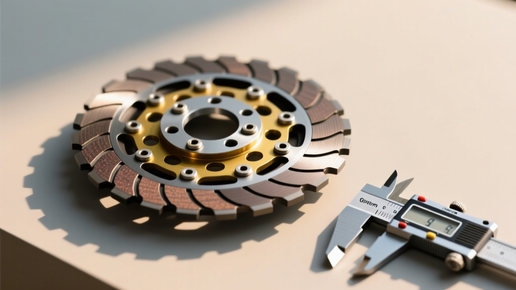
Step height is the precise vertical distance from the pressure plate mounting flange to the friction surface of the flywheel. This measurement dictates the resting position of the diaphragm spring and the subsequent travel of the release bearing. If a machine shop resurfaces a used flywheel and removes 0.030 inches of material from the friction face without correspondingly machining the mounting flange, the step height decreases. This causes the pressure plate to sit closer to the engine block, resulting in incomplete clutch engagement, severe slippage under load, and premature wear on the release bearing.
Conversely, if the step height is too tall—often seen when pairing an aftermarket billet aluminum flywheel with a stock-style pressure plate—the diaphragm spring is over-extended. This leads to a heavy pedal feel, incomplete disengagement (making gear changes impossible), and potential interference between the clutch hub and the crankshaft flange. For example, General Motors LS applications utilizing a T56 Magnum transmission typically require a step height between 0.500 and 0.550 inches. According to McLeod Racing Technical Guides, verifying step height with a straight edge and dial indicator is mandatory before bolting on any new clutch assembly.
Spline Count, Major Diameter, and Hub Interference
Physical compatibility extends beyond the friction surface to the transmission input shaft. The clutch disc hub must perfectly mate with the input shaft splines, both in tooth count and major diameter. A classic Ford T5 transmission utilizes a 1.125-inch 10-spline input shaft, whereas modern Tremec T56 Magnum units use a 1.125-inch or 1.375-inch 26-spline configuration. Installing a 26-spline disc on a 10-spline shaft is an obvious physical impossibility, but subtle hub geometry issues are far more insidious.
Hub protrusion—the distance the clutch hub extends toward the engine block—must be carefully evaluated. In tight bellhousing configurations, an overly protruding hub can strike the crankshaft bolts or the engine block casting, preventing the transmission from seating fully. This misalignment places catastrophic lateral loads on the transmission's front input shaft bearing. Always reference the Tremec T56 Magnum Specifications or your specific transmission manufacturer's blueprint to verify maximum allowable hub protrusion before purchasing a clutch kit.
The Catalog Crossfire: Drivetrain vs. A C Compressor Clutch Kit
During comprehensive engine R&R procedures, technicians and DIYers frequently replace multiple clutch-driven assemblies. This is where modern e-commerce search algorithms create severe purchasing pitfalls. A broad search for 'clutch kit' or 'clutch assembly' often cross-pollinates drivetrain components with HVAC parts, occasionally presenting an a c compressor clutch kit alongside transmission friction discs. While both assemblies utilize friction principles to transfer rotational energy, their engineering parameters, material sciences, and failure modes are entirely distinct. Understanding these differences is vital for buyers navigating poorly filtered online auto parts catalogs.
| Feature | Drivetrain Clutch Kit (e.g., Twin-Disc Ceramic) | A C Compressor Clutch Kit (e.g., Denso/Sanden) |
|---|---|---|
| Primary Function | Engine-to-Transmission Torque Transfer | Compressor Pulley Electromagnetic Engagement |
| Torque Capacity | 800 - 1,500+ lb-ft | 15 - 35 lb-ft |
| Friction Material | Ceramic, Sintered Iron, Kevlar-Organic | Steel-on-Steel, Elastomeric Friction Rings |
| Actuation Method | Hydraulic Throw-out Bearing / Mechanical Linkage | 12V Electromagnetic Coil |
| 2026 Avg. Cost | $850 - $1,600 | $45 - $120 |
When sourcing parts, always filter by the specific transmission model and engine block casting number. An a c compressor clutch kit replaces the electromagnetic coil, pulley bearing, and friction plate on the front of an AC compressor—a critical repair for cabin cooling, but entirely useless for getting power to the rear wheels. For deeper insights into HVAC compressor clutch tolerances, refer to Denso Automotive Compressor Engineering. Always verify the part number against your transmission's specific input shaft requirements, not just the engine application.
Friction Material to Flywheel Metallurgy Mapping
Compatibility also dictates the pairing of the clutch disc's friction material with the flywheel's metallurgical composition. Mismatching these elements guarantees premature failure, severe chatter, or flywheel scoring.
- Organic / Kevlar Discs: Best paired with standard nodular iron or billet aluminum flywheels with steel inserts. These materials offer smooth engagement and are forgiving during daily driving, requiring standard break-in procedures.
- Ceramic / Puck Discs: Require hardened steel flywheels or specially treated nodular iron. Ceramic buttons generate immense localized heat and will rapidly gouge and destroy softer aluminum or untreated iron surfaces. Expect aggressive engagement and low-speed chatter.
- Sintered Iron Discs: Reserved for dedicated drag racing or Pro Mod applications. These must be paired with hardened billet steel flywheels and require high clamp loads from specialized pressure plates. They offer zero slip at high RPM but are entirely unsuitable for street use.
Runout, Bellhousing Alignment, and Final Torque Specs
Even with perfect step height and material compatibility, the assembly will fail if the engine-to-transmission alignment is flawed. Bellhousing runout must be measured using a dial indicator mounted to the engine block, sweeping the inside bore of the bellhousing. Total indicated runout (TIR) should not exceed 0.005 inches. Excessive runout forces the clutch disc hub to oscillate on the input shaft, destroying the transmission's front bearing and causing catastrophic fluid leaks.
When assembling the drivetrain clutch, torque specifications must be followed rigorously. For a standard GM LS application, the flywheel-to-crankshaft bolts (typically M10 or M12) require 74 lb-ft of torque plus an additional 90 degrees of angle torque, utilizing red threadlocker on the threads. The pressure plate-to-flywheel bolts should be torqued to 35 lb-ft in a sequential star pattern to ensure even diaphragm spring loading. Never use an impact wrench to seat a pressure plate, as this will warp the cover and permanently ruin the clamping force distribution.
By prioritizing precise step height measurements, verifying spline geometry, and carefully navigating parts catalogs to avoid irrelevant HVAC components, you ensure a drivetrain build capable of handling modern torque outputs reliably.