The Anatomy of Intermittent AC Compressor Magnetic Clutch Failures
When a vehicle's air conditioning system blows cold air at startup but transitions to warm air after 20 minutes of driving, technicians and DIYers often jump to conclusions about refrigerant charge or compressor failure. However, the root cause is frequently an intermittent failure of the AC compressor magnetic clutch. Unlike the primary friction clutches found in manual transmissions or the torque converter lock-up clutches in automatics, the AC compressor magnetic clutch is an electromagnetic device designed to bridge a precise mechanical air gap to engage the compressor pulley.
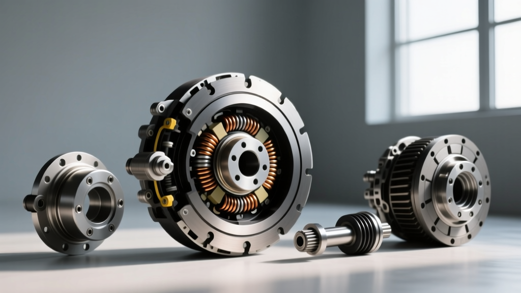
According to technical bulletins published by Mobile Air Climate Systems (MACS), intermittent clutch engagement is rarely a random event; it is a predictable failure tied to thermal dynamics and electromagnetic degradation. The clutch assembly consists of three main components: the electromagnetic coil, the pulley and bearing assembly, and the friction plate (hub). When the PCM or HVAC control module energizes the coil, it generates a magnetic field that pulls the friction plate against the spinning pulley. When this engagement becomes intermittent, it is almost always due to heat soak increasing electrical resistance, a widening mechanical air gap, or a failing control relay.
Step 1: Differentiating PCM Cycling from True Clutch Failure
Before tearing into the clutch assembly, it is critical to differentiate between a failing magnetic clutch and normal system short-cycling commanded by the Powertrain Control Module (PCM). Modern vehicles use complex logic to protect the AC system and optimize engine drivability.
- Low-Pressure Cycling: On systems with an orifice tube and accumulator, the low-pressure switch will intentionally cut power to the clutch coil when suction pressure drops below 22-28 psi to prevent evaporator freezing.
- Evaporator Thermistor Protection: Many late-model vehicles (especially those with Denso 10S17C or GM V5 variable displacement compressors) use a thermistor to cut the clutch relay command if the evaporator core approaches 34°F (1°C).
- Engine Load Shedding: During wide-open throttle (WOT) or severe engine overheating, the PCM will intentionally drop the AC clutch relay ground to free up horsepower and reduce condenser heat load.
Diagnostic Action: Connect a bi-directional OBD2 scan tool and monitor the 'AC Request' and 'AC Relay Command' PIDs. If the scan tool shows the PCM is commanding the relay OFF while the clutch is disengaged, you have a sensor, pressure switch, or PCM logic issue—not a bad clutch. If the PID shows the relay is commanded ON, but the clutch remains disengaged, proceed to electrical and mechanical clutch diagnostics.
Step 2: Electrical Circuit and Relay Voltage Drop Testing
Intermittent voltage drops are notorious for causing clutch slip. The AC clutch coil typically requires a minimum of 11.5 volts to generate sufficient magnetic force to pull the friction plate across the air gap. A failing ISO mini relay in the underhood fuse box can pass enough current to trigger a test light, but fail under the 3-to-5 amp inductive load of the clutch coil.
Perform a dynamic voltage drop test across the clutch connector while the engine is running and the AC is commanded ON. Place your multimeter probes directly on the terminal pins of the clutch connector. If battery voltage is 14.2V at the alternator, but you only read 11.8V at the clutch connector, you have excessive resistance in the wiring harness, a corroded ground splice, or burnt contacts inside the AC compressor clutch relay. Replace the relay and retest before condemning the coil.
Step 3: Thermal Coil Resistance Diagnostics (The Heat Soak Test)
Copper wire exhibits a positive temperature coefficient, meaning its electrical resistance increases as it gets hotter. A marginal clutch coil may measure perfectly within specification when cold in the garage, but fail to engage once subjected to 200°F+ under-hood temperatures and the internal heat generated by the electromagnetic field.
Cold Test: Disconnect the clutch coil connector. Set your multimeter to Ohms (Ω). Measure the resistance across the coil terminals. Compare your reading to the OEM specifications below.
Hot Test: Run the vehicle until the cooling fans cycle and the under-hood temperature is fully saturated. Use an infrared thermometer to verify the compressor housing is above 180°F. Disconnect the connector and immediately measure the resistance. If the resistance spikes more than 25% above the cold specification, or reads open (infinite resistance), the internal coil windings are breaking down under thermal stress. The coil must be replaced.
OEM Clutch Coil Specifications and Air Gap Data
Reference this table for common OEM AC compressor magnetic clutch specifications. Data compiled referencing SAE International HVAC standards and OEM service manuals.
| Compressor Model | Common Applications | Coil Resistance (Cold @ 68°F) | Target Air Gap | Clutch Hub Nut Torque |
|---|---|---|---|---|
| Denso 10S17C / 10PA17C | Toyota, Honda, Lexus | 3.8 Ω to 4.6 Ω | 0.5 mm (0.020 in.) | 11 Nm (8 lb-ft) |
| GM HT6 / V5 Variable | Chevrolet, GMC, Cadillac | 3.2 Ω to 4.5 Ω | 0.6 mm (0.024 in.) | 15 Nm (11 lb-ft) |
| Ford FS-10 / FS-6 | Ford F-150, Mustang, Explorer | 3.4 Ω to 4.8 Ω | 0.5 mm - 0.75 mm | 13 Nm (9.5 lb-ft) |
| Sanden SD7B10 | Subaru, Mazda, Nissan | 3.6 Ω to 4.2 Ω | 0.4 mm - 0.6 mm | 12 Nm (9 lb-ft) |
Step 4: Mechanical Air Gap Measurement and Adjustment
If the electrical circuit is delivering full battery voltage and the coil resistance is within spec, the intermittent failure is likely mechanical. Over tens of thousands of miles, the friction surfaces of the pulley and the clutch plate wear down, widening the air gap. When the gap exceeds 0.035 in. (0.9 mm), the magnetic field weakens exponentially before it reaches the friction plate. The clutch will engage when cold (due to tighter metal tolerances and lower coil resistance), but slip or fail to engage when hot.
Measurement: Use a tapered feeler gauge or a dedicated magnetic clutch gap tool. Slide the gauge between the friction plate and the pulley face at three equidistant points. Adjustment: If the gap is too wide, do not replace the entire compressor. You can often adjust the gap by removing the center hub bolt, pulling the friction plate with a specialized puller, and removing one of the precision shims located on the compressor shaft. Reinstall the plate and re-measure. Target an air gap of exactly 0.020 in. to 0.025 in. (0.5 mm to 0.6 mm) for optimal magnetic transfer without causing drag when disengaged.
Real-World Edge Case: The Snubber Diode Failure
Many modern AC compressor magnetic clutches feature an integrated snubber diode (or suppression diode) wired in parallel with the coil. Its purpose is to absorb the inductive voltage spike generated when the PCM cuts the ground to the relay, protecting sensitive solid-state drivers in the PCM. If this diode begins to leak current in the forward bias direction, it can create a parasitic draw that causes the clutch to drag slightly when disengaged, or cause intermittent relay burnout. If you find yourself repeatedly replacing the AC clutch relay due to melted pin 87 contacts, test the clutch coil for a shorted internal diode using the diode-check function on your multimeter.
Replacement Procedures and Cost Analysis
When diagnosis confirms a failed coil or severely worn friction surfaces, replacement is straightforward and does not require recovering the refrigerant, as the clutch assembly is entirely external to the sealed refrigerant circuit. According to pricing data from the RockAuto Parts Catalog, a complete aftermarket clutch assembly (coil, pulley, and hub) from reputable brands like Four Seasons, UAC, or Denso typically ranges from $65 to $140, depending on the vehicle application. If only the coil is faulty, the coil alone can be sourced for $25 to $45, though pressing the old coil out of the pulley requires a bench press and specialized mandrels.
Installation Torque Specs: When reinstalling the friction plate, the center hub bolt must be torqued precisely to OEM specifications (typically 11 Nm to 15 Nm). Over-torquing can distort the friction plate, causing uneven engagement and severe clutch chatter, while under-torquing will allow the hub to spin on the compressor shaft, destroying the splines. Always use a fresh snap ring to secure the pulley to the compressor snout, ensuring it is fully seated in the groove to prevent catastrophic pulley ejection at highway speeds.