The True Clutch Car Meaning: Why Drag and Release Failures Occur
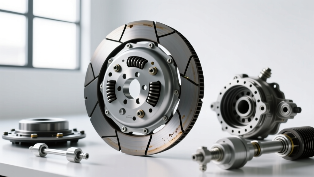
When novice drivers search for the basic 'clutch car meaning,' they are usually met with a simplistic definition: a mechanical coupling that connects and disconnects the engine from the transmission. However, from an advanced diagnostic perspective, the true clutch car meaning revolves around precise hydraulic modulation, friction material coefficients, and strict mechanical clearances. When the disconnection phase fails, the result is clutch drag—a severe condition where the friction disc continues to transmit torque even when the pedal is fully depressed.
Clutch drag leads to gear grinding, an inability to engage first gear while stationary, and accelerated synchronizer ring wear. The root causes typically fall into three categories: hydraulic aeration, mechanical binding on the input shaft, or pressure plate diaphragm fatigue. In this step-by-step guide, we will bypass generic advice and dive deep into the exact measurements, bleeding protocols, and mechanical inspections required to cure clutch drag and release problems.
Step 1: Quantifying Pedal Freeplay and Master Cylinder Pushrod Travel
The most common cause of minor clutch drag is incorrect pedal freeplay. If the master cylinder pushrod is adjusted too tightly against the piston, the fluid return port remains blocked, keeping residual hydraulic pressure in the system. This prevents the release bearing from fully retracting, causing premature wear and slight drag.
Measurement Procedure
- Locate the Dead Zone: Press the clutch pedal by hand. You should feel 10mm to 15mm (0.4 to 0.6 inches) of free travel before resistance from the master cylinder pushrod is felt.
- Adjust the Pushrod: If your vehicle features an adjustable pushrod (common in aftermarket setups like Tilton or Wilwood master cylinders), loosen the jam nut and adjust the clevis to achieve exactly 12mm of freeplay.
- Verify Firewall Flex: On vehicles with sheet-metal firewalls (e.g., Honda K-Series or older Nissan S-chassis), firewall flex can absorb up to 5mm of pedal travel. Install a billet aluminum firewall reinforcement plate to ensure all pedal travel translates directly to master cylinder displacement.
Step 2: Isolating Hydraulic Aeration and Slave Cylinder Stroke Deficits
Hydraulic fluid is incompressible, but air is not. If air becomes trapped in the clutch line, the pedal will feel spongy, and the slave cylinder will not achieve the full stroke necessary to pull the pressure plate fingers away from the friction disc. According to SAE International Standards, hydraulic clutch systems operate under high thermal stress, making fluid selection and bleeding technique critical.
The Reverse-Bleeding Protocol
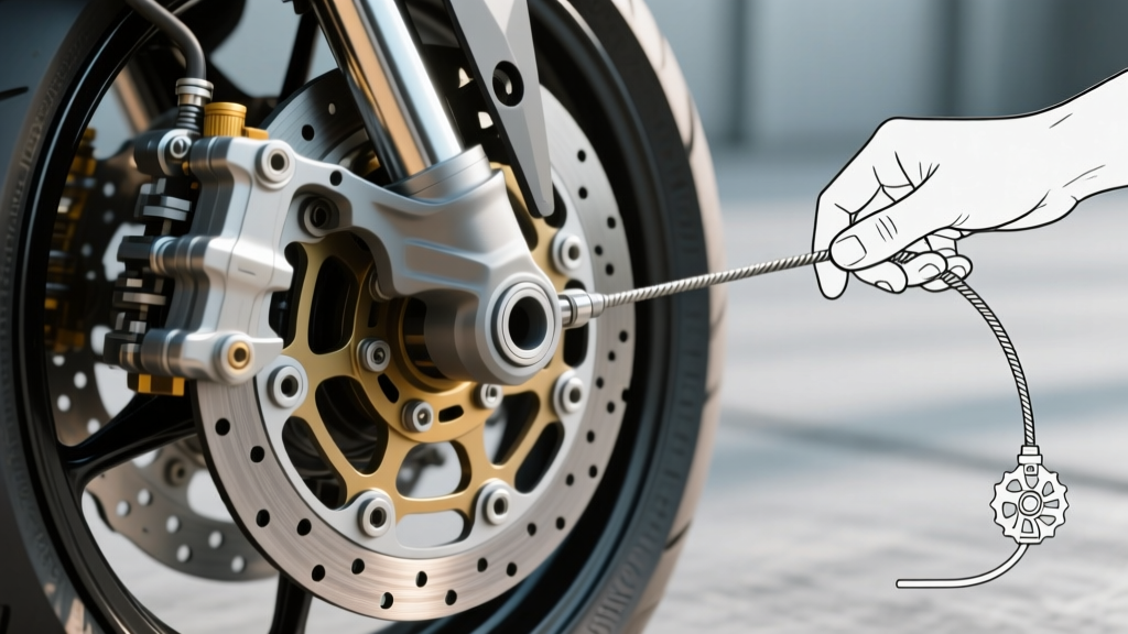
Standard gravity bleeding often fails to push micro-bubbles out of the master cylinder, especially if the line routes upward before descending to the slave cylinder. For a definitive fix, use a reverse bleeder (such as the Motive Products Power Bleeder) to push fluid from the slave cylinder bleed screw up to the master cylinder reservoir.
- Attach the reverse bleeder hose to the slave cylinder bleed nipple.
- Fill the bleeder tank with fresh DOT 4 or DOT 5.1 fluid (avoid DOT 5 silicone fluid, as its high compressibility worsens pedal feel).
- Open the bleed screw and slowly pump fluid upward until no bubbles emerge in the master cylinder reservoir.
- Close the screw and verify slave cylinder stroke. For a Tremec T56 Magnum, full slave travel should measure between 11mm and 14mm.
Step 3: Eliminating Mechanical Binding (Pilot Bearings and Splines)
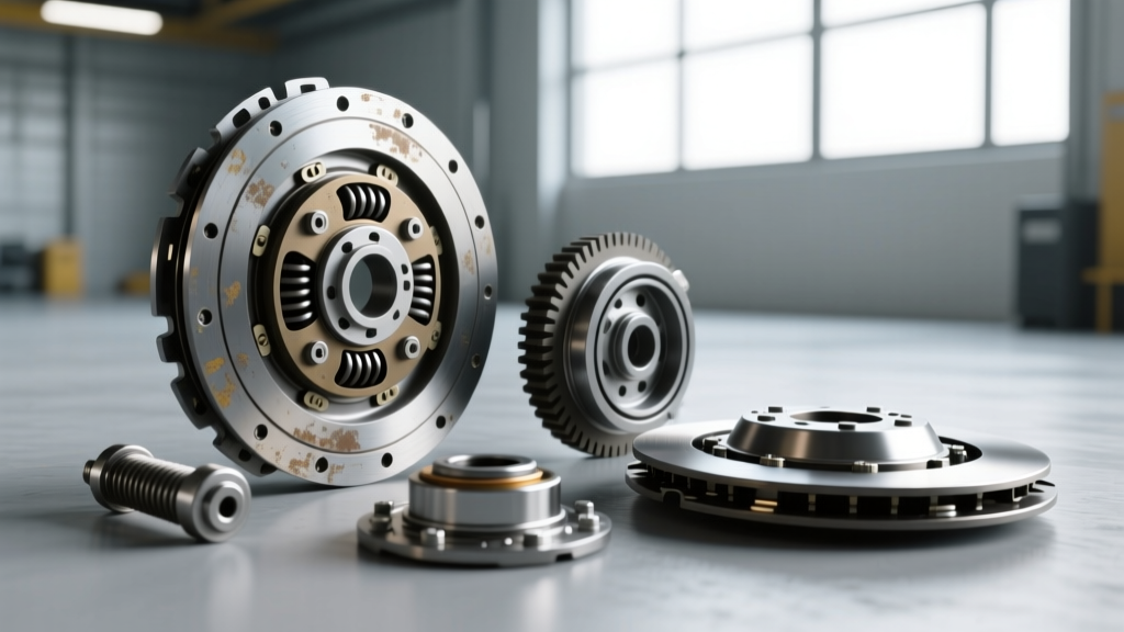
If the hydraulic system is flawless but the clutch still drags, mechanical binding is the culprit. The transmission input shaft must spin freely within the pilot bearing and slide laterally along the splines. If either interface seizes, the disc remains clamped against the flywheel.
Pilot Bearing Extraction and Inspection
A seized pilot bearing will hold the tip of the input shaft, keeping the disc spinning even when the pressure plate releases. Use a dedicated pilot bearing puller with a slide hammer. Never use a blind-hole bearing extractor that expands inside the bearing, as this can score the crankshaft bore.
- Bearing Type Selection: Replace cheap sintered bronze bushings with sealed, high-temperature ball bearings (e.g., NTN or SKF part numbers specific to your crankshaft bore).
- Alignment Check: Misalignment between the engine block and transmission bellhousing causes binding. Use a dial indicator on the bellhousing dowel pins to ensure runout is within 0.005 inches, a specification heavily emphasized by TREMEC Transmission Manuals.
Spline Lubrication Best Practices
Rust or debris on the input shaft splines will trap the friction disc hub. Clean the splines with a brass wire brush and brake cleaner. Apply a microscopic amount of Molykote BR2 Plus or high-molybdenum grease. Warning: Over-greasing the splines will cause grease to sling onto the friction material during high-RPM operation, resulting in catastrophic clutch slip.
Step 4: Measuring Flywheel Runout and Diaphragm Spring Fatigue
When a pressure plate overheats, the diaphragm springs can warp or lose their temper, resulting in uneven clamp load and release. Similarly, a warped flywheel will cause the friction disc to hang up on the high spots during disengagement.
Dial Indicator Runout Test
Mount a magnetic base dial indicator to the engine block and position the stylus against the friction surface of the flywheel. Rotate the crankshaft 360 degrees. According to ZF Group Driveline Technology, maximum allowable flywheel runout is typically 0.005 inches (0.12mm). If runout exceeds this, the flywheel must be resurfaced or replaced.
Expert Note on Dual-Mass Flywheels (DMF): If your vehicle uses a DMF (common in modern diesel and high-torque applications), internal damping springs can collapse, causing severe release issues. DMFs cannot be resurfaced; they must be replaced as a matched set with the clutch kit.
Comparative Diagnostic Data: Common Manual Transmission Platforms
Diagnostic thresholds vary by manufacturer. Refer to the table below for platform-specific release system specifications.
| Transmission Platform | Slave Cylinder Stroke Spec | Pedal Freeplay Target | Common Drag Failure Point |
|---|---|---|---|
| Tremec T56 Magnum (GM LS) | 11.0mm - 14.0mm | 12mm - 18mm | Concentric Slave Cylinder (CSC) internal seal bypass |
| Honda K-Series (Cable Actuated) | N/A (Cable Pull) | 10mm - 15mm | Cable stretch and worn clutch fork pivot ball |
| Ford MT-82 (Mustang GT) | 9.0mm - 11.5mm | 15mm - 20mm | Hydraulic line aeration and weak CSC return spring |
| Porsche G50 (Air/Water Cooled) | 10.0mm - 12.0mm | 15mm - 25mm | Bowden tube flex and degraded pilot bearing |
2026 Repair Cost Analysis and Component Sourcing
Addressing clutch drag requires precise component replacement. In 2026, sourcing high-quality OEM or premium aftermarket kits is critical to avoid repeat failures. Here is what you can expect to invest in a proper repair:
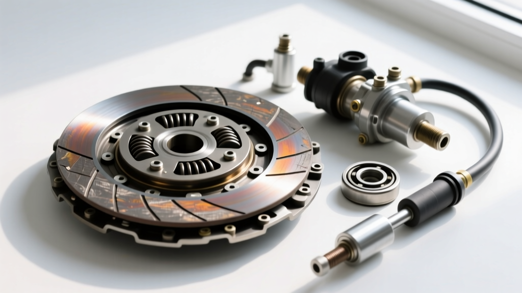
- Premium Clutch Kits (LuK RepSet or Sachs): $350 to $650. These kits include the pressure plate, friction disc, release bearing, and alignment tool. Avoid unbranded kits under $200, as their diaphragm springs frequently warp under thermal load.
- Hydraulic Upgrades: Upgrading to a braided stainless steel clutch line and an adjustable master cylinder (e.g., Wilwood 7/8-inch bore) costs between $180 and $250, drastically improving pedal modulation and eliminating line expansion.
- Machine Shop Services: Flywheel resurfacing typically costs $75 to $120, while bellhousing dowel pin alignment and line-boring can range from $150 to $300.
By systematically measuring freeplay, reverse-bleeding the hydraulics, and verifying mechanical clearances with precision instruments, you eliminate the guesswork from clutch diagnostics. Understanding the true engineering behind the clutch car meaning ensures your manual transmission shifts smoothly and reliably under all driving conditions.