The 'Phantom Pedal' Dilemma: Why the Master Cylinder is Usually the Real Culprit
When a manual transmission clutch pedal drops to the floor or fails to disengage the transmission, the immediate instinct for many DIY mechanics is to crawl under the vehicle and inspect the slave cylinder. However, AA1Car's hydraulic clutch diagnostics consistently show that the root cause of fluid loss or pressure bypass often originates at the firewall. If you are planning on changing the clutch slave cylinder, you must evaluate the entire hydraulic triangle. Replacing a slave cylinder on a system with a fatigued master cylinder will result in immediate re-failure, trapped air, and a spongy pedal.
This comprehensive, step-by-step guide focuses on clutch master cylinder replacement and repair, specifically tailored for modern rear-wheel-drive platforms (such as GM LS-platforms with Tremec T56 or NV4500 transmissions). We will cover exact torque specifications, pushrod free-play adjustments, and the critical bench-bleeding procedures that separate a professional repair from a failed DIY attempt.
Diagnostic Matrix: Master vs. Slave Cylinder Failure
Before ordering parts like the FTE KG19032.1.1 master cylinder or a Sachs SH6209 slave cylinder, verify the failure point using this diagnostic matrix. Misdiagnosis leads to unnecessary transmission removal.
| Symptom | Master Cylinder Fault (Firewall) | Slave Cylinder Fault (Transmission) | Air / Fluid Line Issue |
|---|---|---|---|
| Pedal drops slowly to floor while holding | Internal cup seal bypass (High Probability) | External weeping at fork boot | Air compression in line |
| Pedal feels 'spongy' but returns | Worn primary seal, drawing in air | Failing return spring | Micro-leak at quick-connect fitting |
| Fluid on driver's side floorboard | Rear pushrod boot seal failure | N/A | Hardline corrosion / rub-through |
| Clutch fails to disengage (grinding into gear) | Pushrod out of adjustment (too short) | Concentric slave cylinder (CSC) collapse | Severe fluid loss / empty reservoir |
Required Tools and OEM Components
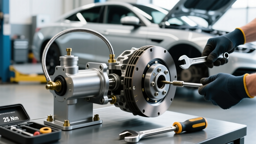
Do not attempt this repair with standard open-end wrenches. Clutch hydraulic lines operate under high pressure and use delicate fittings. Gather the following before starting:
- Replacement Master Cylinder: FTE Automotive or Sachs/LuK (Avoid unbranded $30 internet parts; the internal bypass ports are often machined incorrectly).
- Line Disconnect Tools: 3/4-inch and 5/8-inch quick-connect collar tools (mandatory for GM GMT800/900 and modern Ford applications).
- Wrenches: 11mm and 12mm flare-nut (line) wrenches to prevent rounding soft steel hydraulic fittings.
- Bench Bleed Kit: Includes vice-mounted bracket and recirculation hoses.
- Pressure Bleeder: Motive Products 0108 or equivalent (vacuum bleeders introduce air past the slave cylinder threads).
- Fluid: 1 Liter of high-quality DOT 4 (e.g., ATE Type 200 or Castrol SRF). Never use DOT 5 silicone fluid, as it aerates easily in quick-connect lines and destroys EPDM rubber seals.
Step 1: Depressurization and Firewall Extraction
Evacuating the Reservoir
Use a fluid extractor or a clean turkey baster to remove all brake fluid from the shared clutch/brake reservoir. If your vehicle has a dedicated clutch reservoir, siphon it completely. Place a microfiber towel over the brake master cylinder cap to prevent debris ingress.
Disconnecting the Pushrod
Working under the dashboard, locate the clutch pedal assembly. You will find the master cylinder pushrod attached to the pedal arm via a clevis pin. Remove the retaining hairpin clip or C-clip using needle-nose pliers. Slide the clevis pin out. Pro-Tip: Inspect the clevis pin for grooving. A worn pin will create pedal slop that no hydraulic adjustment can fix.
Removing the Hydraulic Line
Modern vehicles use plastic quick-connect fittings rather than threaded flare nuts. To disconnect the hardline from the back of the master cylinder, push the white or gray plastic collar toward the master cylinder body, then pull the hardline straight out. If your vehicle uses a traditional threaded fitting, use your 11mm flare-nut wrench. Expect to lose roughly 4 ounces of fluid; catch it with a shop rag to prevent paint damage.
Unbolting the Master Cylinder
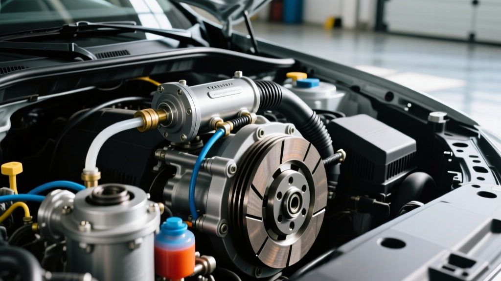
Move to the engine bay. Locate the two 13mm nuts securing the master cylinder to the firewall. These are typically torqued to 15 Nm (11 lb-ft) from the factory. Remove the nuts and gently pull the master cylinder forward and out of the firewall grommet.
Step 2: The Critical Bench-Bleed Procedure
Skip this step, and you will spend three hours under the car trying to bleed a system that is inherently air-locked. According to Schaeffler's LuK technical installation guidelines, dry installation of a hydraulic master cylinder guarantees trapped air in the primary compensation port.
- Secure the new master cylinder in a vice (clamp the mounting flange, never the plastic reservoir or aluminum body).
- Fill the reservoir with fresh DOT 4 fluid.
- Attach the recirculation hoses to the outlet port, routing the other ends so they are submerged in the reservoir fluid.
- Using a blunt punch or dowel, slowly stroke the pushrod inward. You will see large air bubbles escape into the reservoir.
- Release the pushrod slowly. Warning: Releasing it too quickly will cavitate the fluid, creating micro-bubbles that are impossible to purge.
- Repeat this process (roughly 15-20 strokes) until the fluid streams back into the reservoir with zero bubbles.
- Cap the outlet port immediately to prevent fluid drain-back.
Step 3: Installation and Pushrod Free-Play Adjustment
Apply a thin film of silicone dielectric grease to the firewall rubber grommet. Insert the new master cylinder, ensuring the pushrod boot seats perfectly against the firewall to prevent water and abrasive road dust from entering the cabin or destroying the rear seal.
Reinstall the 13mm firewall nuts and torque them to 15 Nm (11 lb-ft). Reconnect the hydraulic hardline until you hear/feel the quick-connect 'click', or torque the flare nut to 18 Nm (13 lb-ft).
Setting Pushrod Clearance
This is where most DIYers fail. The pushrod must have a slight amount of free-play before it contacts the internal piston. If it is pre-loaded, the master cylinder will block the fluid return port, causing the clutch to drag and the transmission to grind into gear. If it is too loose, you lose pedal travel.
Expert Spec: Adjust the clevis on the pushrod so that you feel exactly 1.0mm to 2.0mm of free-play at the pedal pad before resistance is felt. Secure the clevis locknut tightly and reinstall the clevis pin with a brand-new hairpin clip.
Step 4: System Bleeding and Slave Cylinder Integration
If you are simultaneously changing the clutch slave cylinder, now is the time to install the new slave (torquing the bellhousing mounting bolts to 25 Nm) and connect the hardline. Whether you are reusing the old slave or installing a new Concentric Slave Cylinder (CSC), the bleeding methodology remains the same.
The Pressure Bleed Method (Recommended)
Gravity bleeding is insufficient for modern clutch lines due to the upward routing of the hardline over the transmission bellhousing, which creates natural air traps.
- Attach your pressure bleeder to the master reservoir and pressurize to 15 PSI (do not exceed 20 PSI, or you risk blowing out the slave cylinder internal seals).
- Open the bleeder valve on the slave cylinder (typically an 8mm or 10mm hex).
- Allow fluid to flow until it is completely free of bubbles and foam.
- Close the valve, remove the pressure bleeder, and top off the reservoir to the 'MAX' line.
The Reverse Bleed Alternative
If air persists, use a reverse bleeder to inject fluid from the slave cylinder bleeder valve up into the master reservoir. Because air naturally rises, pushing fluid from the bottom up forces air pockets out of the master cylinder's compensation port. Ensure the master reservoir cap is off and monitor the fluid level closely to prevent an overflow onto your engine bay wiring harness.
Post-Repair Validation and Edge Cases
After 50 manual pedal actuations to seat the internal seals, verify the clutch disengagement point. The pedal should engage roughly 1 to 1.5 inches from the floor. If the engagement point is too high, your slave cylinder pushrod may require adjustment (if equipped with an adjustable external slave), or your clutch friction disc is severely worn.
Edge Case - Plastic Line Degradation: On vehicles over 10 years old, the nylon/plastic hydraulic hardlines become brittle from engine bay heat cycles. If the quick-connect fitting leaks immediately after reassembly, do not overtighten. The O-ring inside the quick-connect has likely scored the degraded plastic line. You must replace the entire hardline assembly or splice in a stainless steel braided AN-3 line with a barb fitting.
By treating the clutch hydraulics as a closed-loop system and prioritizing master cylinder bench-bleeding and pushrod geometry, you eliminate the 'phantom pedal' syndrome and ensure crisp, reliable shifts for the life of the clutch assembly.