The Physics of Hydraulic Clutch Ratios
Upgrading a manual transmission or installing a high-clamp-load twin-disc clutch requires more than just bolting in new hardware; it demands a precise hydraulic setup. The relationship between your clutch master cylinder bore size, slave cylinder diameter, and pedal ratio dictates both pedal effort and the physical stroke required to disengage the pressure plate. For 2026 track builds and high-horsepower street cars, miscalculating this ratio results in either a pedal so stiff it causes leg fatigue, or a pedal so long that the clutch drags during high-RPM shifts.
Furthermore, the hydraulic pressure generated by this system places immense stress on the connecting lines. A standard OEM rubber line is rarely sufficient for the volumetric flow and pressure spikes generated by aftermarket bore sizes, making the selection of a high-performance clutch hose a critical secondary step in this process.
Step 1: Calculate Your Required Slave Cylinder Stroke
Before selecting a master cylinder, you must know exactly how far the slave cylinder needs to travel to fully disengage your specific transmission's clutch fork or concentric slave cylinder (CSC).
- Tremec T56 Magnum / Magnum-F: Requires approximately 0.550 to 0.600 inches of effective slave travel.
- Ford MT82 / MT82-D4: Requires roughly 0.650 inches of travel due to the longer throw of the internal fork.
- ZF S5-47 / S6-650 (Heavy Duty Diesels): Can require up to 0.750 inches of travel to overcome heavy diaphragm spring loads.
If your slave cylinder does not meet the minimum travel requirement for your transmission, the clutch will not fully disengage, leading to gear grinding and premature synchro wear. According to Wilwood Engineering's clutch technical guidelines, establishing the required slave stroke is the absolute starting point for any hydraulic calculation.
Step 2: Select the Optimal Master Cylinder Bore Size
The fluid volume displaced by the master cylinder must equal the fluid volume required to move the slave cylinder the necessary distance. The formula for cylinder area is A = π × r².
Let's look at a real-world scenario: You are building a Tremec T56 Magnum swap requiring 0.550 inches of slave travel. You are using a standard 7/8-inch (0.875) bore slave cylinder.
- Slave Area (7/8"): π × (0.4375)² = 0.601 sq in.
- Required Fluid Volume: 0.601 sq in × 0.550 in stroke = 0.330 cubic inches.
Now, we must choose a master cylinder bore that can displace 0.330 cubic inches within a comfortable pedal stroke (typically 1.0 to 1.25 inches at the master cylinder pushrod, dictated by your pedal assembly ratio).
| Master Bore Size | Master Area (sq in) | Required Pushrod Stroke | Pedal Effort (Relative) | Best Application |
|---|---|---|---|---|
| 5/8" (0.625) | 0.307 | 1.07 inches | Lowest (Softest) | Single-disc, light diaphragm springs |
| 3/4" (0.750) | 0.442 | 0.75 inches | Moderate | Twin-disc, T56 Magnum, MT82 |
| 7/8" (0.875) | 0.601 | 0.55 inches | Highest (Stiffest) | Heavy-duty diesel, triple-disc race clutches |
Recommendation: For the T56 Magnum example, a 3/4-inch bore master cylinder (such as the Wilwood 260-1304, retailing around $65) is the ideal choice. It requires only 0.75 inches of pushrod travel, leaving a comfortable margin for pedal over-travel and fluid compression.
Step 3: Sizing and Routing the AN4 Clutch Hose
This is where many builds fail. When you apply 100 lbs of leg force to a pedal with a 6:1 ratio, you generate 600 lbs of force on the master pushrod. Pushing 600 lbs into a 3/4-inch bore (0.442 sq in) generates 1,357 PSI of hydraulic pressure. Under aggressive track braking and shifting, this can easily spike past 1,800 PSI.
OEM rubber hoses suffer from volumetric expansion under these pressures. The hose swells outward instead of transferring the fluid instantly to the slave, resulting in a spongy pedal and delayed clutch engagement. Upgrading to a dedicated performance clutch hose is mandatory.
PTFE vs. Rubber: The 2026 Standard
For modern performance applications, a PTFE (Teflon) lined, stainless steel braided AN4 clutch hose is the industry standard. PTFE offers zero volumetric expansion and handles temperatures up to 500°F, which is critical when the hose is routed near exhaust headers or the transmission bell housing.
- AN3 (3/16" ID): Too restrictive. Causes slow pedal return at high RPM due to fluid flow bottlenecks.
- AN4 (1/4" ID): The optimal size. Balances high-pressure structural integrity with the necessary flow rate for rapid clutch re-engagement.
- AN6 (3/8" ID): Unnecessary for clutches; adds weight and requires excessive fluid volume, making bleeding a nightmare.
When routing your new PTFE clutch hose, maintain a minimum 3-inch clearance from exhaust components. Use fire-sleeve wrapping if the hose must pass within 6 inches of the turbocharger or exhaust manifold. A high-quality AN4 PTFE clutch hose kit with integrated firewall bulkheads typically costs between $85 and $130.
Step 4: Installation and Critical Torque Specs
A common failure mode in upgraded hydraulic systems is firewall flex. If the master cylinder mounting surface flexes under pressure, the pedal will feel spongy regardless of the hose quality. Fabricate or purchase a 1/8-inch thick steel reinforcement plate to sandwich the firewall.
Use the following torque specifications to ensure leak-free, secure connections without stripping aluminum housings or brass fittings:
- Master Cylinder Firewall Nuts (M8 x 1.25): 15 - 18 lb-ft (with reinforcement plate).
- Master Cylinder Pushrod Clevis Pin: Secure with a grade-8 cotter pin; do not overtighten the retaining nut, allow 0.010" of lateral play to prevent binding.
- Banjo Bolt to Master Cylinder (M10 x 1.0): 12 - 15 lb-ft. Always use two new copper or aluminum crush washers.
- AN4 Flare Fittings (Hose to Bulkhead/Slave): 15 - 20 lb-ft. Use a crowfoot wrench to avoid rounding the aluminum hex nuts.
Expert Insight: Never use Teflon tape or liquid thread sealant on AN flare fittings or hydraulic banjo bolts. The seal is made at the flare or the crush washer, not the threads. Sealant will break off inside the system and clog the slave cylinder bleed orifice.
Step 5: Bleeding the System with a Larger Bore
Larger master and slave bores, combined with the low internal volume of an AN4 clutch hose, can trap micro-bubbles that are incredibly difficult to remove via traditional pedal pumping. We strongly recommend reverse bleeding for all aftermarket hydraulic clutch systems.
Fluid Selection
Do not use standard DOT 3 fluid. The high pressures generated by a 3/4-inch or 7/8-inch bore can cause standard fluids to boil or degrade rapidly. According to Motul's fluid engineering data, high-performance DOT 4 or DOT 5.1 fluids offer vastly superior dry boiling points and viscosity stability. Castrol SRF (approx. $35/pint) or Motul RBF 600 are the top choices for heavy-duty clutch hydraulics.
Reverse Bleeding Procedure
- Fill the master cylinder reservoir to the MAX line with your chosen high-temp fluid.
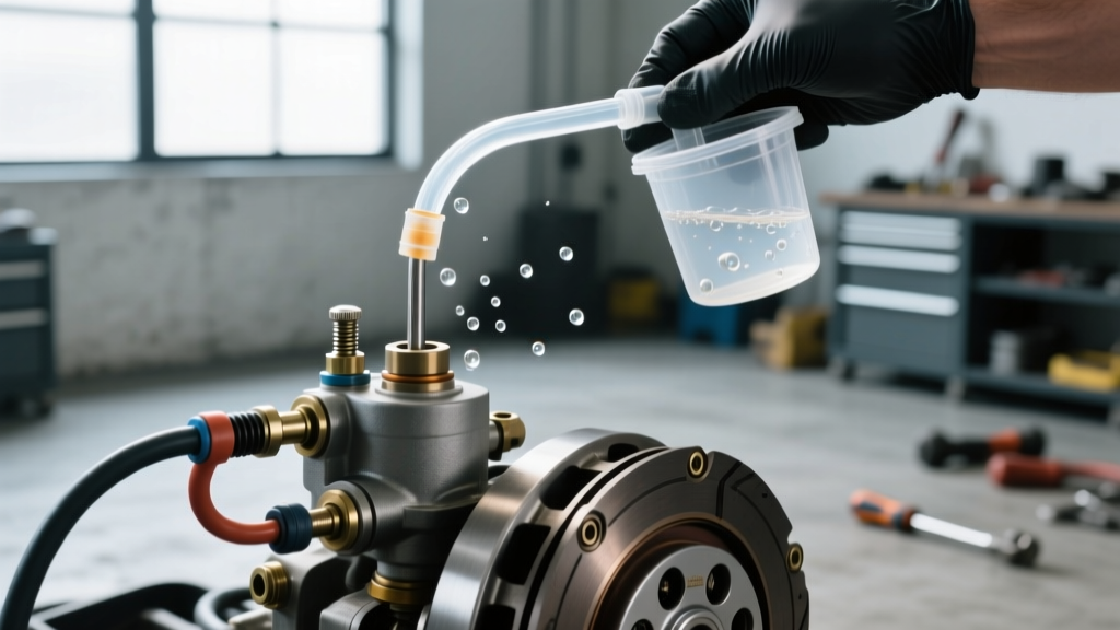
- Attach a reverse bleeder syringe to the slave cylinder bleeder screw using a clear vinyl tube.
- Slowly inject fluid upward through the system. Because air naturally rises, pushing fluid from the bottom forces all trapped air up into the master cylinder reservoir.
- Watch the reservoir closely to prevent overflow. Once no bubbles emerge in the reservoir for 10 continuous seconds, close the slave bleeder screw.
- Cycle the pedal 20 times. If the pedal remains rock-hard with zero sponginess at the top of the stroke, your bore sizing and clutch hose upgrade are perfectly matched.
For further reading on heavy-duty transmission hydraulic requirements, consult the Tilton Racing technical archives, which provide extensive data on racing clutch pedal assemblies and hydraulic ratios.