Diagnosing Failing Clutch Hydraulic Lines
The hydraulic clutch system is a closed-loop circuit operating under extreme pressure variations, often exceeding 1,200 psi during aggressive disengagement. When a clutch pedal feels spongy, drops to the floor, or fails to disengage the transmission, the instinct is to blame the master or slave cylinder. However, the hydraulic line itself is a frequent, yet overlooked, point of failure.
Original Equipment (OE) lines are typically constructed from EPDM (Ethylene Propylene Diene Monomer) rubber. Over time, exposure to engine bay heat cycles, ozone, and hygroscopic fluid contamination causes the inner Teflon or rubber liner to delaminate. This delamination creates a microscopic 'check-valve' effect. Fluid is pushed toward the slave cylinder under high pressure, but the flap blocks the return flow, resulting in a clutch that drags or fails to release. Furthermore, micro-porosity in aging rubber lines allows air to be drawn into the system during the pedal's return stroke, leading to a persistently spongy pedal that mimics a failing master cylinder seal.
Material Science: EPDM Rubber vs. PTFE Braided Stainless
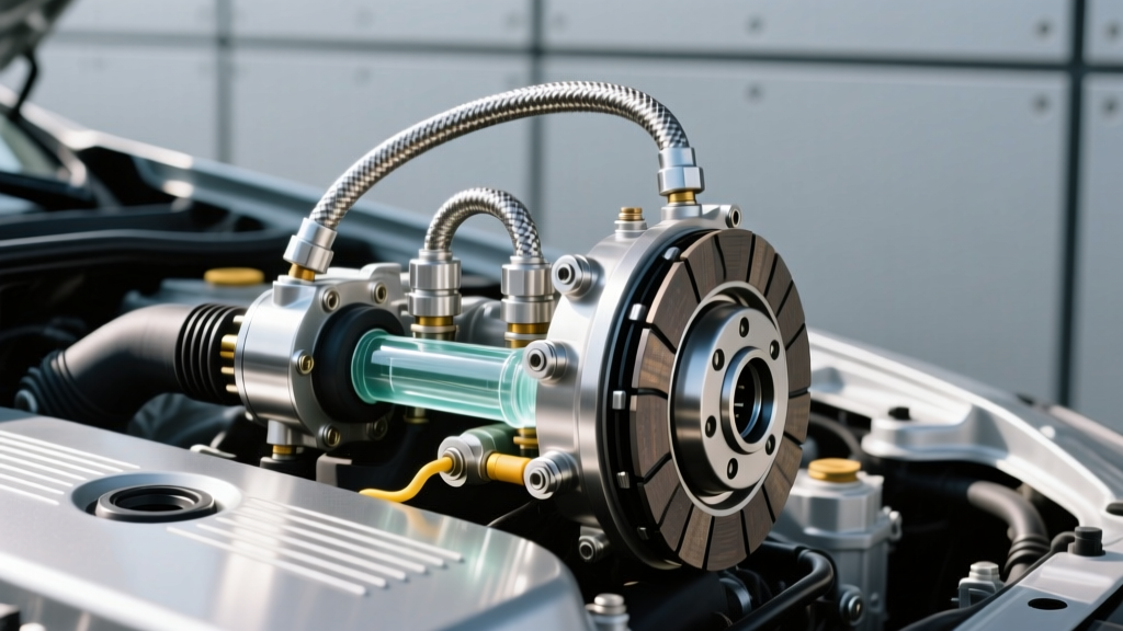
When performing a clutch hydraulic line replacement, upgrading from OE rubber to a PTFE (Polytetrafluoroethylene) stainless steel braided line is the industry best practice for performance and longevity applications. Brands like Goodridge and Russell Performance engineer these lines with an inner PTFE core that exhibits near-zero volumetric expansion under pressure.
Why does this matter? When you depress the clutch pedal, OE rubber lines swell slightly, absorbing a fraction of the hydraulic displacement. This translates to a vague pedal feel and delayed clutch engagement. A braided stainless line ensures 100% of the master cylinder's displacement is transferred instantly to the slave cylinder, providing a crisp, predictable pedal response. Expect to spend between $65 and $140 for a high-quality, DOT-compliant braided clutch line, a worthwhile investment over the $35-$50 OE rubber replacement.
Fitting Standards and Critical Torque Specifications
Stripped threads and crushed banjo washers are the most common errors during line installation. Clutch hydraulic components utilize soft aluminum and brass fittings that are easily destroyed by over-zealous wrenching. Below is the definitive torque chart for standard clutch line fittings.
| Fitting Type | Common Thread / Size | Torque Spec (lb-ft) | Torque Spec (Nm) | Expert Note |
|---|---|---|---|---|
| Banjo Bolt (Master) | M10 x 1.0 | 18 - 22 | 25 - 30 | Always use new copper/aluminum crush washers. |
| Inverted Flare Nut | 3/8"-24 UNF | 11 - 15 | 15 - 20 | Use a flare-nut wrench to prevent rounding. |
| Slave Bleeder Screw | M8 x 1.0 | 7 - 9 | 10 - 12 | Crucial: Over-torquing will snap the bleeder in the casting. |
| Hardline Bracket Bolt | M6 x 1.0 | 7 - 10 | 10 - 14 | Apply medium threadlocker to prevent vibration backing. |
Step-by-Step Line Replacement Protocol
- Depressurize and Drain: Extract as much fluid as possible from the master cylinder reservoir using a fluid syringe. This minimizes spillage when cracking the firewall fitting. Place a catch pan below the bellhousing slave cylinder.
- Remove the Old Line: Unbolt the banjo fitting at the master cylinder. If the line uses a quick-connect fitting at the slave, use a specialized collar-release tool rather than prying with a screwdriver, which will score the O-ring sealing surface.
- Prep the New Line: If installing a braided line, ensure the PTFE core is free of debris. Thread the new banjo bolt with fresh crush washers on both sides of the fitting. The sequence must be: Bolt Head -> Washer -> Line Fitting -> Washer -> Master Cylinder Port.
- Torque and Route: Torque all fittings to the specifications listed above. Route the line away from exhaust headers and steering shafts, securing it with Adel clamps (cushioned P-clips) to prevent chassis chafing.
Mastering the Vacuum Bleed Clutch Procedure
Once the new line is installed, removing the trapped air is paramount. While the traditional 'pump-and-hold' manual bleeding method is common, it is highly detrimental to aging clutch master cylinders. Manually pumping the pedal forces the internal piston to travel into areas of the bore that may have accumulated microscopic corrosion or varnish, instantly tearing the primary lip seal.
This is exactly why experts choose to vacuum bleed clutch hydraulics. By applying negative pressure at the slave cylinder bleeder screw, you draw fluid down from the reservoir through the master cylinder without ever stroking the pedal. This preserves the master cylinder seals and is significantly faster.
Why Vacuum Bleeding Outperforms Manual Pumping
Modern manual transmissions frequently utilize Concentric Slave Cylinders (CSC) housed inside the bellhousing. CSCs are notorious for trapping air pockets in the upper quadrants of the hydraulic circuit. When you vacuum bleed clutch systems using a dedicated tool like the Mityvac MV6840, the continuous, high-volume suction pulls micro-bubbles out of the CSC housing that manual pedal pumping simply cannot dislodge. Furthermore, vacuum bleeding prevents the slave cylinder piston from over-extending and popping out of its bore, a common disaster during manual bleeding if the helper releases the pedal too quickly.
Step-by-Step Vacuum Bleeding
- Tool Setup: Connect your vacuum bleeder to the slave cylinder's bleeder screw. Ensure the master cylinder reservoir is filled to the MAX line with fresh, sealed fluid.
- Pull Vacuum: Pump the vacuum handle until the gauge reads 15 to 20 in-Hg. Watch the gauge for 30 seconds. If the vacuum drops before you open the bleeder, you have a leak at the bleeder threads. Wrap the bleeder threads with a single layer of PTFE tape (leaving the fluid orifice clear) to seal the vacuum.
- Draw Fluid: Open the bleeder screw one-quarter turn. You will see fluid and air bubbles rush into the vacuum canister. Keep a hawk-eye on the master reservoir; never let it run dry, or you will ingest air into the master cylinder port, forcing you to start over.
- Monitor and Close: Once the fluid in the vacuum tube runs completely clear and free of micro-bubbles (usually after pulling 8 to 12 ounces of fluid), close the bleeder screw while maintaining vacuum. This prevents air from being sucked back past the threads as the system equalizes.
Concentric vs. External Slave Cylinder Nuances
When executing a vacuum bleed clutch service, the type of slave cylinder dictates your final verification steps. External slave cylinders (common on older Tremec T-56 or Ford MT-82 applications) feature a visible pushrod. After vacuum bleeding, you can physically measure the pushrod throw to verify hydraulic displacement.
Concentric Slave Cylinders (found in ZF 6-speed, GM 6L80 manual conversions, and most modern European platforms) require a different approach. Because the CSC wraps around the transmission input shaft, you cannot see the piston. After vacuum bleeding, install the transmission, fill the reservoir, and allow the vehicle to sit for 12 hours. The microscopic air bubbles trapped in the CSC will naturally rise up through the hardline and into the reservoir overnight. Top off the fluid the next morning before the first startup to ensure perfect pedal geometry.
Fluid Chemistry and Maintenance Intervals
The fluid you use during the vacuum bleed clutch procedure is just as critical as the bleeding technique. Most domestic and Japanese applications require DOT 3 or DOT 4 glycol-based fluid. DOT 4 is preferred for its higher dry boiling point (446°F / 230°C), which resists vapor lock when the hardline is routed near high-heat exhaust components.
However, never assume DOT fluid is universal. Many European vehicles (BMW, Audi, Porsche) utilize a hydraulic clutch system that shares a reservoir with the brake booster, requiring specific Low Viscosity (LV) DOT 4 or, in select vintage applications, mineral oil (LHM). Flushing a mineral oil system with glycol-based DOT fluid will instantly swell and destroy all rubber seals in the master and slave cylinders. Always verify the cap stamping.
According to SAE International standards, glycol-based clutch fluids are highly hygroscopic, absorbing up to 2% moisture by volume annually. This moisture not only lowers the boiling point but causes internal pitting in the slave cylinder bore. For daily-driven vehicles, a complete hydraulic flush via vacuum extraction every 24 months is the definitive best practice to ensure clutch line longevity and flawless disengagement.