The Hidden Variable in Drivetrain Assembly: Material-Specific Protocols
When dropping a heavy transmission—whether it is a 135-pound Tremec T56 Magnum or a 160-pound ZF S6-650 from a Super Duty—the physical labor often overshadows the micro-precision required at the friction surface. As of 2026, modern CNC-machined billet flywheels and advanced friction compounds have drastically increased torque capacities, but they have also eliminated the margin for installation error. A $600 performance clutch kit can experience catastrophic slip or premature chatter within 500 miles if the installation protocol ignores the specific clutch plate material.
This guide bypasses generic manual instructions and dives into expert-level installation tips, torque specifications, and surface preparation techniques dictated by your chosen friction material.
Flywheel Surface Finish (Ra) vs. Clutch Plate Material
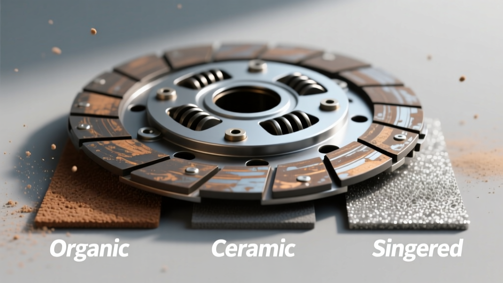
The most critical pre-installation step is matching the flywheel's surface roughness average (Ra) to the clutch plate material. Installing a sintered iron disc on a flywheel finished for an organic pad will result in severe chatter and rapid flywheel scoring. Conversely, an organic disc on a mirror-finish billet steel flywheel will glaze instantly, leading to slip under high boost.
| Clutch Plate Material | Target Flywheel Ra (µin) | Ideal Flywheel Type | Common Applications |
|---|---|---|---|
| Organic (Full-Face) | 15 - 30 µin | Nodular Iron / Steel | Daily Drivers, Light Track (e.g., LuK RepSet) |
| Kevlar / Aramid | 15 - 25 µin | Billet Steel | High-HP Street, Autocross (e.g., ACT HD-KV) |
| Sintered Iron (Puck) | 10 - 15 µin | Billet Steel (Hardened) | Drag Racing, Dedicated Track (e.g., McLeod Metal-lic) |
| Ceramic / Carbon-Carbon | 20 - 30 µin | Billet Steel / Chromoly | Extreme Torque, Twin-Disc (e.g., RXT, Tilton) |
Expert Tip: Always verify the machine shop's Ra finish with a surface profilometer if possible. Many local machine shops default to a 30-40 µin finish for brake rotors, which is far too aggressive for modern Kevlar or sintered clutch plate materials.
Handling, Alignment, and Spline Preservation
The physical handling of the clutch disc during installation varies wildly by material. Organic and Kevlar discs are relatively forgiving, but ceramic and sintered iron pucks are brittle and prone to edge-chipping if dropped on a concrete garage floor. A chipped ceramic puck will create an immediate hot-spot on the flywheel upon first engagement.
Precision Alignment Over Plastic Tools
Throw away the cheap, tapered plastic alignment tool included in most $150 replacement kits. For performance applications, misalignment of even 0.010 inches will cause the transmission input shaft to bind, leading to premature pilot bearing failure and difficult gear engagement.
- Standard Splines: Use a steel dummy shaft matching your transmission. For a Tremec T56 Magnum, this is a 1-1/8' x 26-spline tool. For older Ford T5s, it is 1-1/16' x 10-spline.
- Dial Indicating: When mating the bellhousing (especially on GM LS or Ford Coyote swaps using aftermarket QuickTime bellhousings), use a dial indicator to check runout. SAE International standards mandate a maximum runout of 0.005 inches. Exceeding this will destroy the input shaft and clutch plate material unevenly.
Torque Specifications and Fastener Protocols
Applying the correct torque to the pressure plate is non-negotiable. Uneven torque warps the diaphragm springs, altering the clamp load and causing uneven wear across the clutch plate material.
Application-Specific Torque Specs
Always tighten pressure plate bolts in a crisscross, star pattern, drawing the unit down in 5 lb-ft increments to ensure the pressure plate seats perfectly flat against the flywheel.
- GM LS Series (M8 x 1.25 Bolts): 35 lb-ft (47 Nm)
- Ford Modular / Coyote (M8 Bolts): 25 - 30 lb-ft (34 - 40 Nm)
- Nissan SR20DET / RB25 (M8 Bolts): 22 - 25 lb-ft (30 - 34 Nm)
- Porsche G50 / 996 (M8 Bolts): 18 lb-ft (25 Nm)
Chemical Retention Warning: Do not use standard blue Loctite 242 on pressure plate bolts if the block or flywheel has been cleaned with brake cleaner or oil. In 2026, the industry standard is Loctite 243, which is oil-tolerant and provides reliable threadlocking even if minor contamination is present in the blind holes of the flywheel.
Hydraulic Throwout Bearing Preload & Bleeding
If your installation involves a hydraulic release bearing (HRB)—common in modern GM LS and Honda K-Series swaps—air in the system or incorrect preload will ruin the clutch plate material before you even leave the driveway.
For internal HRBs (like the McLeod or Tilton units), you must measure the air gap. Using a dial caliper, measure the distance from the bellhousing mounting face to the clutch fingers, and subtract the bearing's compressed height. The ideal air gap is typically 0.100' to 0.150'. If the gap is zero, the bearing is constantly riding on the diaphragm fingers, generating immense heat that will bake the organic or Kevlar clutch plate material from the inside out.
When bleeding the system, use a pressure bleeder set to 15 PSI. Gravity bleeding is insufficient for complex lines with multiple high-points, leading to a spongy pedal that prevents full clutch disengagement and causes gear-grind.
The Break-In Procedure: Sealing the Deal
The installation is not complete until the clutch plate material is properly bedded to the flywheel. The bedding process transfers a microscopic layer of friction material onto the flywheel's pores, creating the actual gripping surface.
Material-Specific Break-In Frameworks
| Material | Break-In Distance | Heat Cycling Method |
|---|---|---|
| Organic | 300 - 500 Miles | Normal city driving; avoid WOT or heavy towing. |
| Kevlar / Aramid | 500 - 1000 Miles | Kevlar requires higher heat to glaze properly. Include moderate highway pulls and gradual stops. |
| Sintered Iron | 10 - 20 Slips | Perform controlled, low-speed (20-30 mph) slip-engagements in a safe area to burn off manufacturing oils and seat the metallic pores. |
| Carbon-Carbon | Track-Only Heat Cycles | Requires extreme heat (400°F+) to reach optimal coefficient of friction. Do not drive on the street until track-bedded. |
For authoritative data on bedding procedures and material limits, always consult manufacturer technical bulletins, such as those provided by Advanced Clutch Technology (ACT) and McLeod Racing Tech Support. Additionally, referencing RAM Clutches Technical Information is invaluable for understanding hydraulic bearing clearances during twin-disc setups.
Final Inspection Checklist
Before reinstalling the driveshaft and lowering the vehicle, verify the following:
- Flywheel ring gear teeth are chamfered on the correct side for the starter bendix.
- Clutch fork pivot ball is properly torqued and greased with high-temp moly grease (not standard chassis lube, which melts and contaminates the disc).
- Throwout bearing collar moves freely on the transmission input shaft retainer without binding.
By treating the clutch plate material as the defining variable in your installation protocol, you ensure maximum torque transfer, smooth engagement, and a drivetrain that survives the rigors of modern high-performance driving.