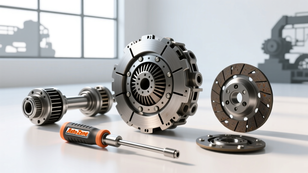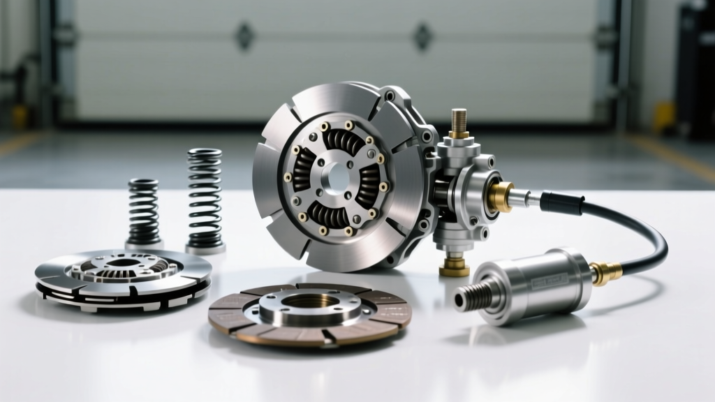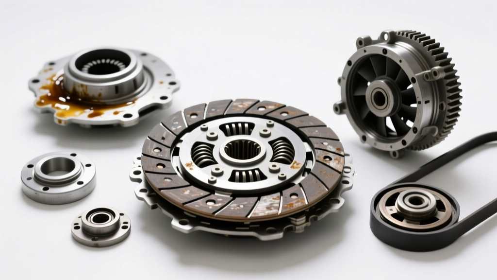
Beyond the Pedal: Defining the Modern Clutch Ecosystem
While most automotive enthusiasts associate the word 'clutch' strictly with manual transmission flywheel assemblies, the mechanical reality of modern powertrains involves multiple torque-transferring couplings. The engine cooling fan clutch—a viscous or electronically controlled fluid coupling—is a critical component that dictates thermal management and parasitic horsepower loss. In this comprehensive diagnostic guide and buyer’s comparison, we will perform a deep-dive root cause analysis into both drivetrain and fan clutch failure modes, and provide a masterclass on how to change fan clutch units across light-duty and Class 8 heavy-duty applications in 2026.
Drivetrain Clutch Failure Modes & Root Cause Analysis
Drivetrain clutches, whether found in a traditional manual transmission or a heavy-duty automated manual transmission (AMT) like the Eaton Endurant or Volvo I-Shift, rely on precise friction coefficients and clamping force. When these systems fail, the root cause is rarely isolated to the friction disc itself.
Thermal Glazing and Resin Outgassing
Organic clutch facings are bound by phenolic resins designed to withstand operational temperatures up to 250°C (482°F). During severe slip events—such as heavy towing or improper launch control—surface temperatures can spike past 450°C. This causes the resin to outgas and carbonize, creating a hardened, glass-like surface known as thermal glazing. The root cause is typically inadequate clamping force from a fatigued diaphragm spring or an undersized clutch assembly for the vehicle's modified torque output.
Diaphragm Spring Hysteresis and Wear Grooves
According to engineering data from Eaton Corporation, premature release bearing wear is often misdiagnosed as a transmission input shaft issue. In reality, it is a failure of the diaphragm spring fingers. If the clutch pedal free-play is incorrectly adjusted (or if a hydraulic concentric slave cylinder fails to fully retract), the release bearing rides constantly against the spring fingers. This generates localized friction, cutting deep wear grooves into the spring steel and ultimately causing catastrophic clamping pressure loss.
Engine Fan Clutch Failure Modes (Viscous & Electronic)
Engine fan clutches transfer rotational energy from the water pump hub to the cooling fan using either a viscous silicone fluid shear or an electronic magnetic coil. Understanding their failure modes is critical for preventing engine overheating and eliminating parasitic drivetrain drag.
Polydimethylsiloxane (PDMS) Shear Breakdown
Viscous fan clutches utilize a highly specific polydimethylsiloxane (PDMS) silicone fluid. Over 100,000+ miles of continuous shearing between the internal rotor and the clutch housing, the long-chain polymers in the PDMS fluid physically break down. This mechanical degradation reduces the fluid's kinematic viscosity, resulting in a fan clutch that slips excessively and fails to pull adequate CFM (cubic feet per minute) of air through the radiator stack under heavy load.
Bimetallic Strip Calibration Drift & Solenoid Burnout
Thermostatic fan clutches rely on a front-mounted bimetallic coil that expands and contracts based on ambient radiator air temperature. Over time, thermal cycling causes calibration drift, meaning the clutch may not engage until the coolant is already at critical temperatures. In modern electronically controlled clutches (like the Horton DriveMaster), the internal electromagnetic solenoid or the PWM (Pulse Width Modulation) wiring harness is subjected to extreme under-hood heat, frequently leading to coil burnout and a default 'limp-home' engaged state, which robs the engine of 15 to 20 horsepower.
Root Cause Analysis Matrix: Diagnostic Quick-Reference
| Symptom | Clutch Type | Primary Root Cause | Diagnostic Metric / Test |
|---|---|---|---|
| High-RPM Slip / Shudder | Drivetrain (Manual) | Oil contamination or thermal glazing on facings | Measure flywheel runout (Max 0.004 in); inspect rear main seal |
| Engine Overheating at Idle | Viscous Fan Clutch | PDMS fluid shear breakdown or low fluid volume | Resistance test: Fan should spin 1 to 1.5 revolutions when hot and engine is off |
| Excessive Parasitic Drag / Roaring | Electronic Fan Clutch | PWM solenoid short or bimetallic strip seized | Scan for HVAC/ECM codes; verify 12V/PWM signal at harness pigtail |
| Chatter on Engagement | Drivetrain (Twin-Disc) | Uneven pressure plate wear or flywheel hot spots | Check diaphragm spring finger height variance (Max 0.020 in) |
Buyer’s Guide: Sourcing Replacement Clutches in 2026
When sourcing replacement components, the market is divided between OEM, premium aftermarket, and economy remanufactured units. For critical thermal management and drivetrain longevity, avoiding white-box economy parts is paramount.
- Premium OEM / Tier 1 (Horton, Sachs, ZF): Expect to pay between $450 and $850 for heavy-duty electronic fan clutches, and $600 to $1,400 for drivetrain clutch kits. These units feature aerospace-grade PDMS fluids and forged steel pressure plates. Horton Inc. remains the gold standard for Class 8 fan drives.
- Premium Aftermarket (ACDelco, Exedy, Motorcraft): Priced between $180 and $350 for light-duty fan clutches, and $300 to $800 for drivetrain kits. Excellent for stock replacement on vehicles like the GM 6.6L Duramax or Ford 7.3L Godzilla.
- Economy / Remanufactured ($90 - $150): Often feature recycled housings with poorly calibrated bimetallic strips. Not recommended for towing or commercial applications due to high failure rates within the first 20,000 miles.
Masterclass: How to Change Fan Clutch Assemblies
Knowing how to change fan clutch hardware safely requires specialized tooling and an understanding of rotational thread dynamics. The following procedure applies to common light/medium-duty applications (e.g., GM 6.6L Duramax, Ford 6.7L Powerstroke).
Step 1: Tooling and Thread Direction Verification
You will need a dedicated fan clutch wrench set (such as the OTC 4553 or Lisle 12100). Critical Warning: Verify thread direction before applying force. Many OEM water pump hubs utilize a left-hand thread (counter-clockwise to loosen) to prevent the clutch hub from unscrewing due to the engine's rotational inertia. GM Duramax applications typically use a standard right-hand thread, while many Ford and Cummins applications use left-hand threads. Consult the factory service manual via SAE International standards or OEM documentation.
Step 2: Extraction and Belt Routing
Use a 1/2-inch breaker bar on the serpentine belt tensioner to relieve tension and slip the belt off the water pump/fan pulley. Place your wrench on the water pump hub flats and your secondary wrench on the fan clutch nut. Strike the secondary wrench sharply with a dead-blow mallet to break the initial torque seal. Avoid using excessive heat.
Expert Diagnostic Tip: Never attempt to heat a viscous fan clutch hub with an oxy-acetylene torch to break it free. Temperatures exceeding 250°F (121°C) will permanently destroy the internal PDMS silicone fluid matrix and warp the bimetallic actuator coil, ruining the new or salvageable unit.
Step 3: Installation and Torque Specifications
Clean the water pump hub mating surface with isopropyl alcohol to remove any oxidized aluminum or steel particulate. Thread the new fan clutch hub onto the water pump by hand to prevent cross-threading. Torque specifications vary wildly by application:
- GM 6.6L Duramax (Light/Medium Duty): 47 lb-ft (64 Nm)
- Ford 6.7L Powerstroke: 85 lb-ft (115 Nm) - Left Hand Thread
- Cummins ISX15 (Class 8 Heavy Duty Hub Nut): 125 lb-ft to 140 lb-ft (169 - 190 Nm)
Reinstall the serpentine belt, ensuring the ribs are perfectly seated in the alternator and tensioner grooves. Start the engine and allow it to reach operating temperature. Use an infrared pyrometer to verify that the fan clutch housing temperature rises in correlation with the radiator outlet temperature, confirming proper bimetallic or electronic engagement.
Preventative Diagnostics and Fluid Dynamics
Clutch systems—whether transferring 1,200 lb-ft of torque to a drivetrain or managing 30,000 CFM of airflow across a radiator—are victims of thermal and mechanical entropy. By understanding the root causes of PDMS shear breakdown and diaphragm spring hysteresis, technicians and enthusiasts can move beyond reactive part-swapping and implement predictive maintenance strategies. Always prioritize OEM-specification fluid couplings and adhere strictly to dynamic torque sequences to ensure powertrain longevity in the demanding operational environments of 2026.