The Hidden Culprit Behind Performance Clutch Chatter
When building a high-performance manual drivetrain for the 2026 track season, enthusiasts often obsess over friction materials, flywheel mass, and pressure plate clamp load. Yet, a violent, shuddering engagement—commonly known as clutch chatter—frequently persists even after installing a premium twin-disc setup. While mechanical factors like an unsprung hub or a warped flywheel are common suspects, modern performance builds introduce a critical electronic variable: the clutch switch. In an era where standalone ECUs manage launch control, flat-foot shifting, and automated rev-matching, a poorly calibrated or failing clutch switch can induce severe driveline shock that mimics mechanical chatter.
Clutch chatter is fundamentally a stick-slip friction phenomenon occurring at frequencies between 15 Hz and 30 Hz. However, when your ECU misinterprets the exact millisecond of clutch engagement due to a faulty switch signal, it can aggressively cut ignition or manipulate the throttle body at the wrong moment. This electronic misfire creates a torque reversal that violently shakes the chassis, leading tuners and mechanics on a wild goose chase for mechanical faults that do not exist. Understanding the intersection of hydraulic pedal geometry, switch actuation, and ECU logic is paramount for eliminating vibration in high-torque applications.
How the Clutch Switch Dictates Driveline Shock
In a factory vehicle, the clutch switch serves a rudimentary purpose: preventing the starter from engaging unless the pedal is depressed, and canceling cruise control. In a performance context—whether you are running a Holley Terminator X, a Link G4X, or a MoTeC M150—the clutch switch is a primary input for drivetrain management. When you upgrade to an aggressive clutch kit, such as the McLeod RST or an ACT Xtreme twin-disc, the pedal's engagement point often shifts. Factory plunger-style switches are notoriously non-adjustable and prone to internal spring fatigue.
If the clutch switch triggers too late in the pedal's travel, the ECU may keep the launch control RPM limiter active a fraction of a second too long. When the clutch finally bites, the sudden release of stored kinetic energy overwhelms the friction disc's damping capacity, resulting in aggressive chatter. Conversely, if the switch 'bounces' or exhibits micro-interruptions due to pedal vibration, the ECU may rapidly toggle the ignition retard table on and off. This electronic stutter translates directly into physical vibration through the engine mounts and transmission tunnel.
The Physics of Chatter in Upgraded Drivetrains
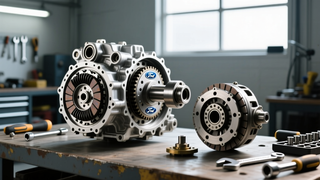
To diagnose the issue accurately, we must separate mechanical chatter from electronic driveline shock. Mechanical chatter occurs when the coefficient of friction (COF) between the disc and the flywheel fluctuates rapidly. This is common with sintered iron or cerametallic materials that require high operating temperatures to achieve a stable COF. According to McLeod Racing's technical documentation, twin-disc clutches with unsprung hubs transmit significantly more NVH (Noise, Vibration, and Harshness) to the chassis because they lack the torsional dampening springs found in organic street discs. When you pair an unsprung hub with an improperly timed clutch switch signal during an auto-blip downshift, the resulting RPM mismatch forces the driveline to absorb the shock, manifesting as a violent, chatter-like vibration.
Diagnosing Switch-Induced Vibration vs. Mechanical Chatter
Before tearing down the transmission to inspect the pressure plate, you must isolate the root cause. Use the following diagnostic framework to determine if your vibration is mechanical or switch-induced.
| Diagnostic Parameter | Mechanical Clutch Chatter | Switch-Induced Driveline Shock |
|---|---|---|
| Occurrence Trigger | Happens consistently during normal take-off from a dead stop, especially when cold. | Occurs primarily during launch control engagement, flat-foot shifts, or ECU rev-matching. |
| Vibration Frequency | Steady 15-30 Hz shudder felt through the seat and steering wheel. | Erratic, sharp jolts or high-frequency electrical stutter felt as a misfire or bog. |
| Datalogging Evidence | Switch state transitions cleanly; RPM and MAP sensors show physical oscillation. | ECU logs show 'Clutch Switch' state bouncing (0 to 1 rapidly) or launch retard lingering. |
| Pedal Feel | Pedal may pulsate rhythmically against the driver's foot during engagement. | Pedal feels normal, but engagement point does not match the ECU's assumed switch point. |
Performance Upgrade Path: Adjustable Clutch Switches
Eliminating switch-induced chatter requires replacing the brittle OEM plastic plunger with a precision, adjustable switch mechanism. For high-horsepower builds utilizing an adjustable pedal stop (common in drag racing and time-attack), the switch must be independently calibrated to trigger exactly 2-3mm before the clutch begins to disengage the flywheel.
For GM LS/LT and Ford Coyote swaps, fabricators frequently utilize sealed micro-switches, such as the Omron D2F-01F, mounted on a custom CNC-machined aluminum bracket. These switches feature a gold-alloy crossbar contact capable of handling the low-voltage, high-speed data polling of modern ECUs without signal degradation. Alternatively, the Standard Motor Products S803 adjustable push-rod switch offers a bolt-in solution for many GM applications, allowing for precise thread-based calibration of the engagement window.
Installation and Torque Specifications
When upgrading the switch and verifying the mechanical components, adherence to exact torque specifications is non-negotiable. A warped flywheel or unevenly torqued pressure plate will guarantee mechanical chatter, regardless of how perfectly your clutch switch is tuned.
- Flywheel to Crankshaft (ARP 2000 Bolts): 80 lb-ft (108 Nm) using a calibrated torque wrench in a star pattern. Always use a new harmonic damper bolt if applicable.
- Pressure Plate to Flywheel (M8 Bolts): 35 lb-ft (47 Nm). Tighten gradually in a crisscross pattern to prevent warping the diaphragm spring, which causes uneven clamp load and subsequent chatter.
- Clutch Switch Bracket Fasteners: Use Grade 8 or Class 10.9 hardware with medium-strength threadlocker (Loctite 243) to prevent high-frequency pedal vibrations from loosening the switch mount.
ECU Calibration for Launch Control and Rev-Matching
Hardware is only half the battle. The 2026 standard for performance tuning demands rigorous filtering of the clutch switch input within the ECU software. According to the Holley Terminator X configuration manuals, raw switch inputs from the track environment are highly susceptible to electrical noise and mechanical bounce.
To prevent the ECU from interpreting pedal vibration as a rapid engagement/disengagement event (which causes ignition cut flutter and severe driveline shock), you must configure the Debounce Filter. Set the switch debounce time to a minimum of 15ms to 20ms. This tells the ECU to ignore any signal state changes that occur faster than 20 milliseconds, effectively filtering out the physical vibration of the pedal assembly.
Furthermore, map your ignition retard and fuel enrichment tables to correlate with the exact pedal travel percentage where the clutch switch activates. If your switch triggers at 10% pedal travel, but the clutch doesn't physically release until 25%, the ECU's launch control logic will be misaligned with the mechanical reality, resulting in a violent, shuddering launch. Utilize a linear potentiometer (pedal travel sensor) wired into an analog input to overlay physical pedal position against the digital clutch switch state in your datalogs.
Summary Checklist for Track-Ready Engagement
Before heading to the track or dyno, run through this diagnostic checklist to ensure your drivetrain is free of both mechanical and electronic chatter:
- Verify Mechanical Baseline: Confirm flywheel runout is within 0.005 inches and pressure plate bolts are torqued to 35 lb-ft.
- Upgrade the Switch: Replace OEM plastic plungers with adjustable, sealed micro-switches or heavy-duty push-rod variants.
- Calibrate the Deadband: Adjust the switch push-rod so it triggers 2mm before the throw-out bearing contacts the diaphragm fingers.
- Apply ECU Debounce: Set a 15ms-20ms debounce filter in your standalone ECU to eliminate signal bounce.
- Datalog the Engagement: Record a pull and verify that the launch control RPM limit drops precisely as the clutch switch state changes, with no erratic ignition cut flutter.
By treating the clutch switch not as a mere safety interlock, but as a critical drivetrain management sensor, you can eliminate phantom vibrations, protect your driveline from catastrophic shock loads, and achieve the buttery-smooth, high-torque engagement required for modern performance driving.