Clarifying Terminology: Twin-Plate Hardware vs. The Driving Technique
When veteran diesel technicians and fleet managers discuss a double clutch tractor trailer system, they are navigating a semantic overlap unique to the heavy-duty trucking industry. On the road, 'double clutching' refers to the manual shifting technique required to match input and output shaft speeds on non-synchronized transmissions, such as the legendary Eaton Fuller 13-speed and 18-speed manuals. However, from a mechanical diagnostic standpoint, the 'double clutch' refers to the twin-plate (double-disc) clutch assembly housed within the SAE #1 bell housing. Modern high-torque diesel engines—like the Cummins X15 (producing up to 2,050 lb-ft of torque) and the Detroit DD15—demand the immense friction surface area that only a twin-plate clutch can provide without exceeding standard bell housing diameter constraints.
This technical deep-dive provides a comprehensive clutch system inspection checklist for Class 8 tractor-trailers. Whether you are diagnosing a driver's complaint of 'hard shifting' (which forces them to double-clutch the gears) or performing a preventative tear-down of an Eaton Solo 40 or Spicer twin-plate assembly, this guide delivers the exact OEM specifications, wear limits, and diagnostic frameworks required for heavy-duty drivetrain maintenance.
Phase 1: Cab Diagnostics & Pedal Free Travel
Before dropping the inspection pan or pulling the transmission, the most critical clutch system diagnostics begin in the cab. Incorrect pedal geometry is the leading cause of premature twin-plate clutch failure and clutch brake destruction.
1. Pedal Free Travel Verification
Free travel is the distance the clutch pedal moves before the release bearing contacts the clutch brake or pressure plate fingers. For heavy-duty mechanical linkages, the spec is strictly 1.5 to 2.0 inches. If free travel is less than 1.5 inches, the release bearing rides constantly on the pressure plate, generating immense heat and leading to catastrophic bearing seizure. If it exceeds 2.0 inches, the clutch will not fully disengage, causing gear clashing and forcing the driver to double-clutch every shift.
2. Clutch Brake Squeeze Measurement
The clutch brake is designed to stop the transmission input shaft from spinning when the truck is stationary, allowing for smooth first-gear engagement. Measure the distance from the floor (or firewall stop) to the pedal when the clutch brake engages. The required clutch brake squeeze is 0.5 to 0.75 inches. If the squeeze is greater than 1.0 inch, the clutch brake cannot apply sufficient friction to the input shaft, resulting in grinding when shifting into gear from a standstill.
Phase 2: Under-Hood & Bell Housing Inspection Protocol
With the cab linkage verified, move to the bell housing inspection cover (drop pan). This area reveals the mechanical translation of pedal force to the twin-plate assembly. Inspect the following components using calibrated micrometers and dial indicators.
| Component | Measurement Point | Maximum Wear Limit | Corrective Action |
|---|---|---|---|
| Release Bearing Wear Pad | Thickness of the contact face | 0.125 inches (wear) | Replace bearing assembly if worn beyond limit |
| Clutch Fork Pads | Where fork contacts the bearing | 0.060 inches (groove depth) | Replace fork; inspect cross-shaft for scoring |
| Cross-Shaft Bushings | Radial play of the shaft | 0.030 inches (TIR) | Replace bushings and seals to prevent linkage bind |
| Clutch Brake Disc | Friction material thickness | 0.060 inches remaining | Replace clutch brake and resurface mating collar |
Release Bearing Travel Verification
Using a specialized clutch setting gauge (or a fabricated dial indicator mount), measure the actual travel of the release bearing when the pedal is fully depressed. For most 15.5-inch Eaton and Meritor twin-plate setups, maximum bearing travel should be 0.50 to 0.55 inches. Exceeding this travel over-stresses the internal marcel springs of the friction discs and can cause the intermediate plate to crack.
Phase 3: Internal Twin-Plate Clutch Measurements
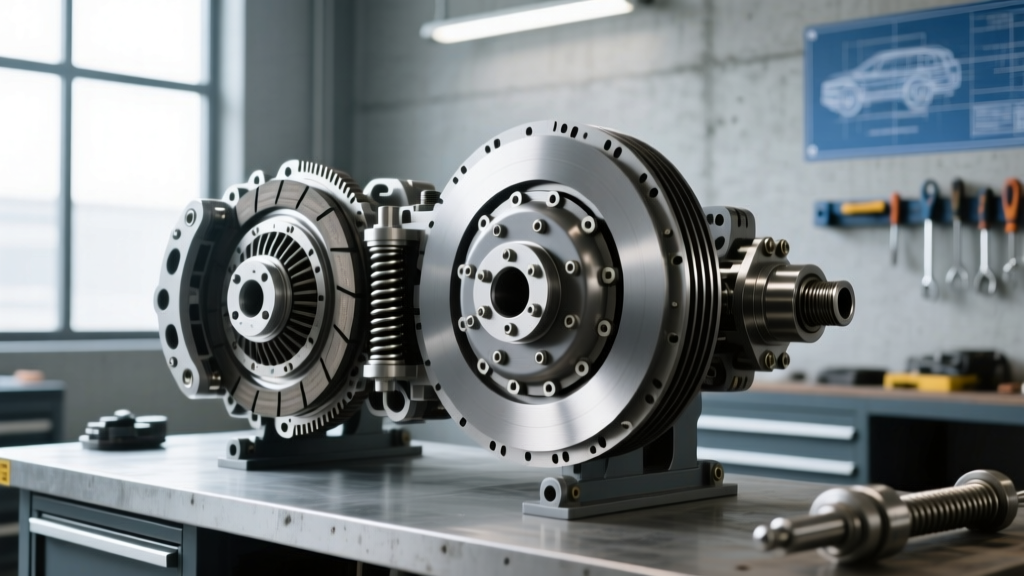
When symptoms point to internal failure—such as severe driveline chatter, clutch drag, or complete loss of torque transfer—the transmission must be separated from the engine. The twin-plate clutch assembly introduces a unique variable not found in passenger vehicles: the intermediate plate.
Flywheel Runout & Intermediate Plate Float
The intermediate plate floats between the two friction discs, driven by lugs on the flywheel and the pressure plate. Mount a dial indicator to the engine block and measure the flywheel face runout. The maximum allowable Total Indicator Reading (TIR) is 0.005 inches. If the flywheel exceeds this runout, the intermediate plate will wobble at high RPM, destroying the drive straps and causing a violent chatter upon clutch engagement.
Drive Lug Wear Limits
Inspect the drive lugs on both the flywheel and the intermediate plate. These lugs transfer the engine's rotational force. Over time, they develop wear notches. If the notch depth exceeds 0.030 inches, the intermediate plate will bind and fail to retract when the clutch is depressed. This binding causes 'clutch drag,' making it impossible for the driver to stop the input shaft, thereby forcing them to double-clutch to avoid gear grinding.
Friction Disc Thickness Specifications
Measure both the front and rear friction discs at their thinnest points. While specifications vary slightly by manufacturer (e.g., Eaton part # 863240Y vs. Spicer equivalents), a standard new 15.5-inch twin-plate friction disc measures approximately 0.380 inches thick. The absolute minimum wear limit is 0.310 inches per disc. If either disc is below this threshold, or if the splines exhibit excessive radial lash (more than 0.015 inches of rotational play on the transmission input shaft), a complete clutch pack replacement is mandatory.
Technician Note: Never reuse the intermediate plate if the friction discs are being replaced due to heat checking or glazing. The intermediate plate absorbs immense thermal shock and often develops microscopic warping that will instantly ruin new friction material upon reassembly. Always replace the clutch pack as a matched set. For more on matched heavy-duty drivetrain components, refer to Eaton Heavy-Duty Clutch Systems guidelines.
Common Twin-Plate Failure Modes & Driveline Symptoms
Understanding the symptoms of twin-plate failure allows technicians to diagnose the root cause before the transmission is ever unbolted.
- Clutch Chatter on Engagement: Usually caused by oil contamination on the friction discs (often from a leaking engine rear main seal or transmission input shaft seal), broken marcel springs within the friction disc, or excessive flywheel runout.
- Clutch Drag (Grinding in Neutral): The clutch is not fully releasing. Causes include a warped intermediate plate, binding drive lugs, or a hydraulically compromised clutch master cylinder failing to provide full stroke to the release fork.
- Clutch Slipping Under Load: Common in high-horsepower applications (e.g., heavy haul or logging). Caused by worn friction discs, a fatigued pressure plate diaphragm spring, or incorrect pedal free travel preventing full clamp load.
- Vibration at High RPM: Often a symptom of failing intermediate plate drive straps or a severely out-of-balance clutch assembly. This requires immediate attention to prevent bell housing fracture.
Hydraulic AMT vs. Mechanical Linkage Considerations
The modern Class 8 landscape is dominated by Automated Manual Transmissions (AMTs) like the Volvo I-Shift, Mack mDRIVE, and Eaton Endurant HD. While the internal twin-plate clutch hardware remains fundamentally similar, the actuation differs. Instead of a mechanical cross-shaft and fork, AMTs utilize a Concentric Slave Cylinder (CSC) or a pneumatic/hydraulic clutch actuator module. When performing a double clutch tractor trailer inspection on an AMT, technicians must plug into the OEM diagnostic software (e.g., Mack Premium Tech Tool) to monitor the clutch actuator position sensor and perform a 'Clutch Bite Point Adaptation' after any mechanical inspection or replacement. Failing to recalibrate the bite point will result in harsh shifts and premature wear to the new twin-plate assembly.
Torque Specifications & Reassembly Standards
Reassembling a heavy-duty twin-plate clutch requires strict adherence to torque sequences. The mass and rotational forces involved mean that even minor deviations can lead to catastrophic driveline failure. Below are standard baseline specifications for a typical Cummins X15 / Eaton 15.5-inch setup. Always verify against the specific OEM service manual, such as those available via Cummins X15 Efficiency Series documentation.
| Fastener Location | Torque Specification | Notes & Sequence |
|---|---|---|
| Flywheel to Crankshaft | 175 lb-ft + 90 degrees | Star pattern; use new OEM torque-to-yield bolts |
| Pressure Plate to Flywheel | 70 - 85 lb-ft | Star pattern; align intermediate plate drive lugs |
| Bell Housing to Engine Block (SAE #1) | 100 - 120 lb-ft | Clean mating surfaces; verify alignment dowels |
| Transmission to Bell Housing | 130 - 150 lb-ft | Support transmission fully to avoid input shaft binding |
For fleets operating specialized heavy-haul configurations, consulting Mack Trucks Parts & Services or equivalent OEM portals ensures that high-torque clutch variants (such as those rated for 2,250 lb-ft) are installed with the correct heavy-duty pressure plate springs and reinforced drive straps.
Summary
Inspecting a double clutch tractor trailer system requires moving beyond basic visual checks. By systematically verifying pedal free travel, measuring clutch brake squeeze, quantifying bell housing wear limits, and strictly adhering to intermediate plate and flywheel runout tolerances, technicians can accurately diagnose driveline symptoms. Proper execution of this checklist prevents premature twin-plate failures, eliminates the need for drivers to manually double-clutch due to mechanical drag, and ensures maximum uptime for Class 8 fleet operations.