Understanding the Aftermarket Blue Torque Converter
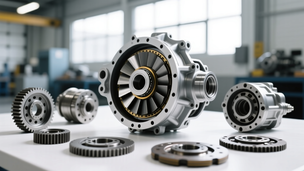
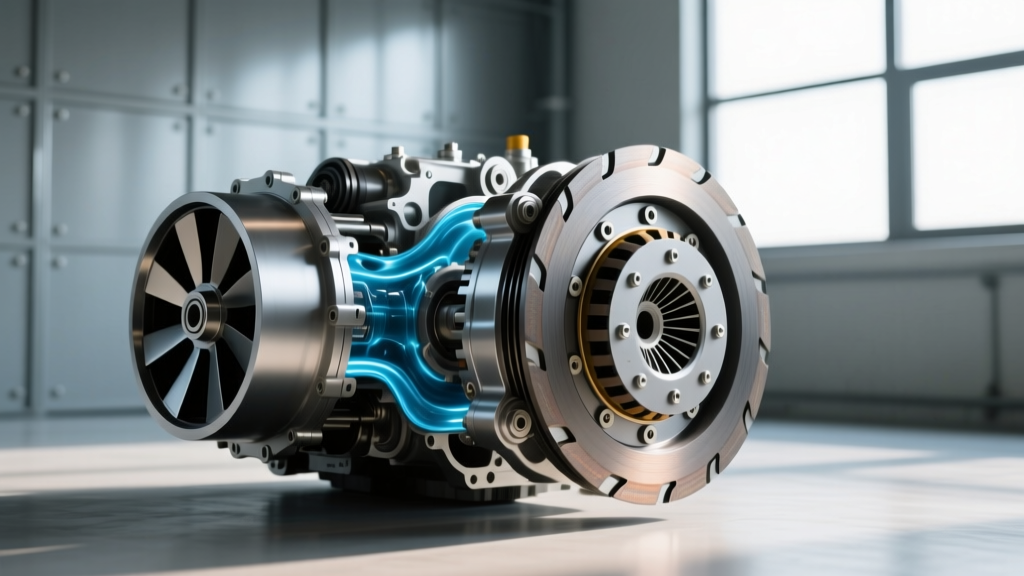
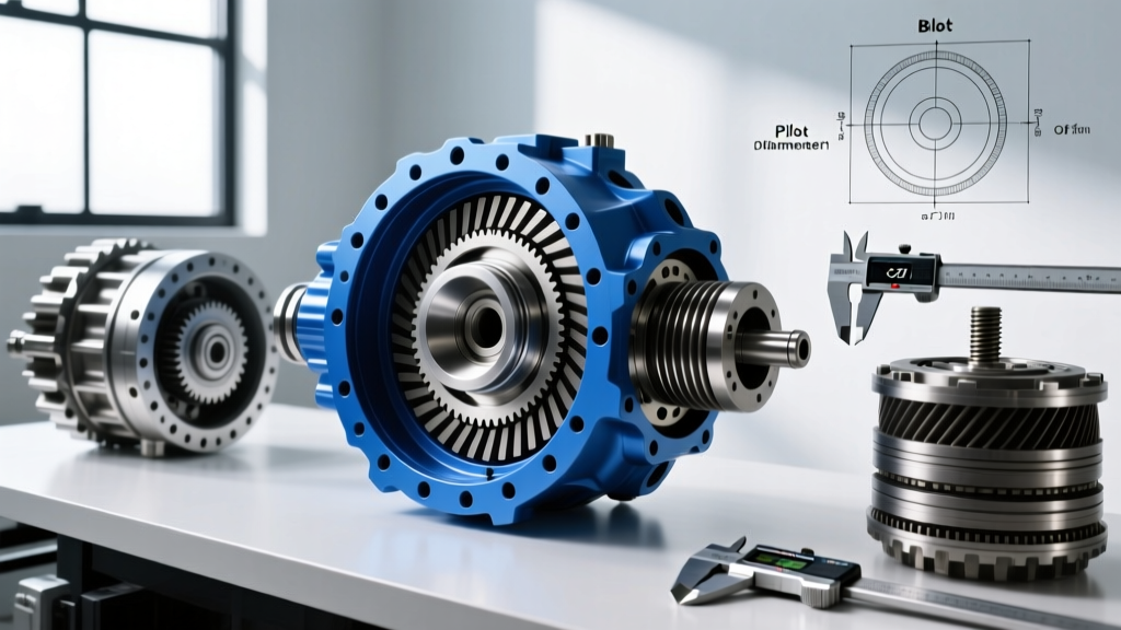
When performance enthusiasts and professional transmission builders refer to a 'blue torque converter,' they are typically referencing high-capacity, TIG-welded aftermarket units finished in a specialized blue thermal powder coat or anodized blue billet aluminum. Unlike OEM stamped-steel converters that rely on spot-welding and are prone to ballooning under high boost or nitrous applications, these blue-coated billet converters are engineered to handle 800 to 1,500+ horsepower. The blue powder coat is not merely aesthetic; it serves as a thermal barrier and corrosion inhibitor, aiding in heat dissipation during extreme stall-speed slip conditions.
However, upgrading from a factory stamped unit to a heavy-duty billet blue torque converter introduces critical fitment variables. The transition requires precise attention to bolt patterns, flexplate mating surfaces, pilot diameters, and crankshaft flange offsets. A miscalculation of even 0.030 inches in offset or a mismatched bolt circle will result in catastrophic drivetrain failure. This technical deep-dive explores the exact fitment parameters, bolt pattern matrices, and the specific drivetrain symptoms that arise when these tolerances are ignored.
The Anatomy of Torque Converter Fitment
Before bolting a high-stall blue converter to your flexplate, you must verify three primary dimensional interfaces. According to TCI Automotive's engineering guidelines, ignoring any of these three dimensions will lead to immediate front pump destruction or flexplate fatigue.
- Pilot Diameter: The machined hub at the front of the converter that centers it inside the engine crankshaft bore. Common diameters include 1.703 inches (GM LS/LT), 1.375 inches (Ford Modular), and 1.250 inches (Ford Small Block).
- Bolt Circle and Pattern: The arrangement of the mounting pads. OEM converters often use 3-bolt or 4-bolt patterns, while aftermarket billet units frequently require a 6-bolt flexplate for increased clamping force and load distribution.
- Pad Offset (Pull-Away): The distance from the transmission bellhousing mating surface to the converter's flexplate mounting pads. Proper offset ensures the converter is fully seated in the transmission oil pump without binding against the flexplate.
Bolt Pattern Matrix: GM, Ford, and ZF Applications
The shift from an OEM converter to an aftermarket blue unit often necessitates a flexplate upgrade. Below is a comparative matrix detailing the bolt pattern specifications for popular platforms when utilizing high-horsepower billet converters.
| Transmission / Platform | OEM Bolt Pattern | Aftermarket Blue Spec | Flexplate-to-Crank Torque | Converter Nut Torque |
|---|---|---|---|---|
| GM 4L60E / 4L80E (SBC/BBC) | 3-Bolt (11.5" Circle) | 6-Bolt Billet (11.5") | 65 lb-ft (w/ Loctite 263) | 30-35 lb-ft (3/8"-24) |
| GM 6L80E / 6L90E (LS/LT V8) | 6-Bolt (Metric) | 6-Bolt Billet (M10x1.5) | 65 lb-ft (w/ Loctite 263) | 35 lb-ft (M10x1.5) |
| Ford 4R70W / C6 (Modular V8) | 4-Bolt (10.5" Circle) | 4-Bolt / 6-Bolt Adapter | 60-65 lb-ft | 28-32 lb-ft (3/8"-24) |
| ZF 8HP70 / 8HP90 (Gen 2/3) | 4-Bolt Torx (Integrated) | Billet Damper Hub | 59 lb-ft (M10x1.25) | N/A (Torx T50 @ 22 lb-ft) |
Note: When adapting a 6-bolt blue converter to an engine originally equipped with a 3-bolt flexplate (such as early GM Gen III LS engines), you must install a dedicated 6-bolt SFI-certified flexplate. Drilling your OEM flexplate to accept 6 bolts will compromise the metallurgical integrity and lead to high-RPM fragmentation.
Step-by-Step Fitment and Clearance Verification
Measuring Crankshaft Flange Offset and Runout
Before installing the flexplate, measure the crankshaft flange runout using a dial indicator. SAE International technical papers on powertrain NVH (Noise, Vibration, and Harshness) dictate that crank flange runout must not exceed 0.003 inches TIR (Total Indicator Reading). If the flange is warped, the flexplate will dish when torqued, altering the converter pad offset and inducing severe axial preload on the transmission's front pump thrust bearing.
Verifying Pilot Diameter and Bushing Tolerances
The pilot hub of a blue torque converter is typically CNC-machined from billet steel to a specific diameter. However, crankshaft pilot bores can wear or become egg-shaped over time.
- GM Applications: The standard pilot bore is 1.703 inches. If your aftermarket converter features a 1.701-inch pilot, it relies on a tight interference fit or a bronze pilot bushing. Never force a converter into the crank; if it requires a dead-blow hammer, the pilot is binding, which will instantly destroy the front pump gear upon startup.
- Clearance Spec: Aim for 0.001 to 0.002 inches of clearance between the converter pilot and the crank bore or bushing. Use plastigauge or a dial bore gauge to verify this before final assembly.
Calculating Pad Offset (The Pull-Away Test)
With the transmission bolted to the engine block (without the flexplate attached), slide the blue torque converter fully into the transmission pump. You should feel three distinct 'clunks' as the converter passes through the turbine spline, the stator support, and finally seats into the pump drive gear.
Once fully seated, measure the distance from the transmission bellhousing mating surface to the converter's mounting pad. Compare this to the distance from the engine block mating surface to the flexplate mounting surface. The flexplate must sit 1/8-inch (0.125") to 3/16-inch (0.187") away from the converter pad when the transmission is pulled flush to the engine block. This gap is closed by the converter nuts, which preloads the converter forward against the internal thrust bearing. If there is zero gap, the converter is bottoming out in the pump, guaranteeing pump failure within the first 50 miles.
Diagnosing Fitment Failure Symptoms
Because incorrect torque converter fitment directly impacts hydraulic pressure and mechanical alignment, it manifests as distinct drivetrain symptoms. Recognizing these symptoms early can save a $3,000 transmission rebuild.
Symptom 1: High-RPM TCC Shudder and Apply Fatigue
If the pad offset is incorrect and the converter is preloaded too far backward (away from the engine), the Torque Converter Clutch (TCC) apply piston cannot achieve full hydraulic stroke. In 6L80E and ZF 8HP applications, this results in a violent shudder between 1,500 and 2,000 RPM during light throttle application. The TCC is slipping because the converter is physically pulled away from the TCC friction surface by the flexplate tension. This is often misdiagnosed as a bad TCC solenoid or degraded fluid, when in reality, the flexplate offset is incorrect.
Symptom 2: Front Pump Bushing and Gear Shearing
A classic symptom of pilot diameter mismatch or crank flange runout is the rapid destruction of the front pump bushing. If the converter pilot is not perfectly concentric with the crankshaft, the converter orbits slightly at high RPM. This orbital whipping action tears the soft bronze or babbitt material out of the front pump bushing. Once the bushing fails, the pump gear loses its centering, leading to the shearing of the pump drive tangs and an immediate loss of line pressure. You will hear a distinct metallic 'grinding' or 'whirring' noise emanating from the bellhousing that changes pitch with engine RPM, not vehicle speed.
Symptom 3: Flexplate Cracking and Starter Engagement Issues
When an enthusiast forces a 4-bolt Ford blue converter onto a mismatched flexplate using adapter washers or elongated slots, the clamping force is unevenly distributed. Under the torsional shock of a 600+ HP launch, the flexplate will develop micro-fractures radiating outward from the bolt holes. A secondary symptom of a warped or improperly offset flexplate is intermittent starter engagement; the flexplate dishes under load, altering the ring gear's mesh depth with the starter Bendix, resulting in a harsh 'grinding' noise during cranking.
Torque Specifications and Fastener Selection
Never reuse OEM torque converter nuts when installing a billet blue unit. The cyclic loading of a high-stall converter will stretch OEM-grade hardware. Always use ARP or equivalent Grade 8 / Class 10.9 flange nuts.
- GM LS/LT Flexplate to Crank: 65 lb-ft. Must use red Loctite (263) on the threads. The OEM bolts are often torque-to-yield (TTY) and should be replaced with aftermarket ARP bolts torqued to 70 lb-ft.
- GM M10 Converter Nuts: 35 lb-ft. Apply a medium-strength thread locker (Blue Loctite 243) to prevent vibration-induced backing out.
- Ford Modular Flexplate to Crank: 60 lb-ft. Ensure the dowel pin on the crankshaft flange is perfectly aligned with the flexplate indexing hole to maintain neutral balance.
- ZF 8HP Torx Bolts: Modern 2026 ZF 8HP Gen 3 applications utilize specialized Torx T50 bolts to secure the integrated damper hub to the billet converter cover. These are torqued to exactly 22 lb-ft (30 Nm). Over-torquing will strip the aluminum threads in the converter cover, requiring a costly TIG-weld repair.
Conclusion
Upgrading to a high-horsepower blue torque converter is one of the most effective ways to multiply torque and handle extreme power levels in modern and classic platforms. However, the structural integrity of the entire drivetrain relies on the millimeter-perfect execution of bolt patterns, pilot clearances, and pad offsets. By utilizing a dial indicator, verifying your flexplate bolt circle, and adhering strictly to manufacturer torque specifications, you ensure that your billet converter delivers power to the wheels rather than destroying the front pump. For further reading on powertrain dynamics and aftermarket component integration, consult the Summit Racing Expert Advice archives and always reference your specific transmission builder's blueprint sheet before final assembly.