The Fashion vs. Friction Reality Check
If your recent search history included the Jacquemus Rond Carré clutch, you have likely experienced a hilarious collision between Parisian high fashion and heavy-duty automotive mechanics. The Jacquemus Rond Carré is a highly sought-after leather handbag, not a component you can bolt to a Tremec T56 Magnum or a ZF S6-53 transmission. However, if you are a driver, mechanic, or enthusiast who landed here because you are actually experiencing automotive clutch slip, chatter, or pedal degradation, you are in the right place.
At AutoGearNexus, we do not deal in calfskin leather or brass hardware. We deal in maraging steel, Kevlar-infused organic friction materials, and hydraulic concentric slave cylinders. In this technical deep-dive, we will decode the actual wear signs and lifespan indicators of a manual transmission clutch system, providing you with the exact measurements, torque specifications, and diagnostic frameworks needed to evaluate your drivetrain's health in 2026.
The Physics of Clutch Degradation: Energy Over Mileage
Amateur diagnostics often rely on mileage to predict clutch lifespan (e.g., 'it is time for a replacement at 60,000 miles'). Senior drivetrain engineers know this is a fallacy. Clutch wear is fundamentally a function of kinetic energy dissipation, measured in Joules.
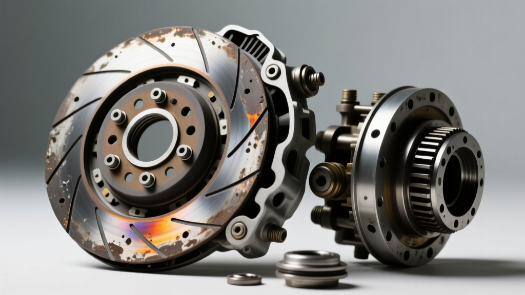
When you slip a clutch to move a 4,200 lb vehicle from a standstill at 2,500 RPM, the friction disc must absorb and convert the difference in rotational energy into thermal energy. A single aggressive launch or sustained slipping in stop-and-go traffic can generate surface temperatures exceeding 800°F (426°C) on the friction face. This thermal cycling leads to three primary failure modes:
- Glazing: The organic resins in the friction material melt and recrystallize, creating a glass-like surface that severely drops the coefficient of friction (μ).
- Thermal Cracking: Rapid expansion and contraction cause micro-fissures in the cast-iron pressure plate and flywheel friction surfaces.
- Diaphragm Spring Fatigue: Prolonged heat exposure reduces the spring steel's yield strength, resulting in inadequate clamping force even if the friction material remains thick.
Quantifiable Friction Material Wear Metrics
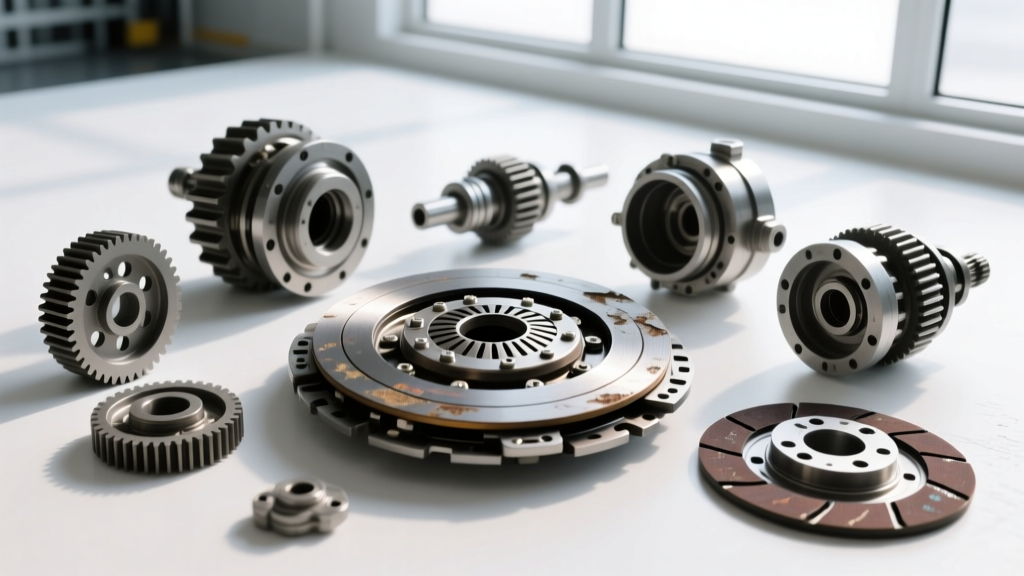
Visual inspection of a removed clutch disc is the only definitive way to measure lifespan consumption, but understanding the baseline specifications is critical for machine shop evaluation and teardown analysis.
Standard Organic Disc Specifications
Let us look at a standard 240mm organic clutch disc (such as the LuK 323 0271 09 commonly found in European and domestic applications):
- New Total Thickness: Typically 8.2mm to 8.8mm (measured from the outer edge of the friction material, excluding the damper springs).
- Service Wear Limit: Replacement is mandated when the total thickness drops below 7.0mm, or when the friction material is worn to within 0.3mm of the steel rivet heads.
- Runout Tolerance: Maximum allowable lateral runout on a new disc is 0.5mm. If a removed disc shows runout exceeding 1.2mm, the input shaft splines or the damper hub are likely compromised.
'A clutch disc does not fail simply because it is thin; it fails because the damper springs lose their torsional elasticity, leading to driveline shunt and premature transmission bearing wear.' — Driveline NVH Engineering Guidelines
5-Point Technical Diagnostic Matrix
Before pulling the transmission, use this diagnostic matrix to isolate the failing component based on driver feedback and physical pedal metrics.
| Symptom | Probable Root Cause | Diagnostic Metric / Test | Action Threshold |
|---|---|---|---|
| Slipping under high load (3rd/4th gear) | Friction glazing or weak diaphragm spring | Stall test in 4th gear at 2,000 RPM | Engine RPM rises without proportional vehicle speed increase |
| Chatter on engagement (1st/Reverse) | Contaminated friction surface or broken damper springs | Visual inspection for oil ingress; check engine/trans mounts | Any ATF or gear oil on friction face requires rear main seal or input shaft seal replacement |
| Pedal sticking to the floor | Internal CSC (Concentric Slave Cylinder) seal failure | Check master cylinder fluid level; inspect bellhousing for weeping | Fluid loss with no external hose leaks indicates internal CSC bore scoring |
| Difficulty engaging gears (Synchro clash) | Clutch drag / incomplete release | Measure clutch pedal freeplay and hydraulic travel | Less than 0.5 inches of freeplay or failure to bleed hydraulic air |
| Rhythmic ticking at idle (clutch depressed) | Worn CSC bearing or dry input shaft pilot bearing | Stethoscope on bellhousing; noise changes with pedal load | Replace CSC and pilot bearing during any clutch R&R procedure |
Dual-Mass Flywheel (DMF) Wear: The Hidden Lifespan Killer
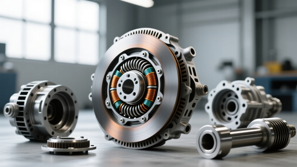
In modern manual transmissions (especially diesel applications and high-torque EcoBoost engines), the clutch is mated to a Dual-Mass Flywheel. The DMF absorbs torsional vibrations that would otherwise shatter gear teeth. However, DMFs have a strict lifespan, typically aligning with the second clutch replacement (approx. 100,000 - 120,000 miles).
DMF Freeplay and Runout Specifications
According to data published via the Schaeffler REP (Repair, Explanations, and Practice) Portal, reusing a worn DMF with a new clutch kit is the leading cause of premature clutch failure and NVH (Noise, Vibration, and Harshness) complaints.
- Tangential Freeplay: Using a specialized gear-testing tool, measure the rotational freeplay of the secondary flywheel mass. The absolute maximum limit is typically 20 degrees (or roughly 4-5 gear teeth depending on the ring gear count). Exceeding this means the internal grease has broken down and the arc springs are collapsed.
- Axial Play (Rock):strong> Measured with a dial indicator on the outer edge of the secondary mass. Maximum allowable axial play is usually 1.6mm.
- Radial Runout: Must not exceed 1.2mm. If the DMF surface is blued from heat spotting, it cannot be resurfaced. DMFs must be replaced, never machined.
Concentric Slave Cylinder (CSC) Hydraulics
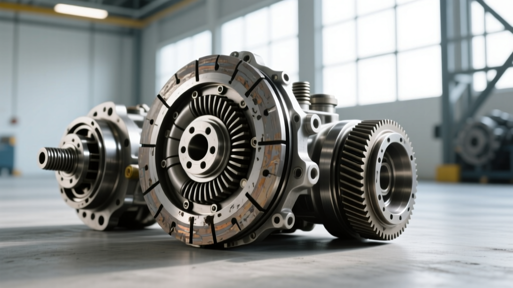
The modern clutch pedal relies on a hydraulic CSC located inside the bellhousing. Unlike older external fork-and-throwout-bearing setups, the CSC is a sealed unit that rides constantly on the pressure plate fingers. If your clutch pedal feels spongy, or if the engagement point suddenly moves closer to the floor, the internal seals of the CSC have likely worn a groove into the aluminum bore.
Technical Directive: Never attempt to 'flush and bleed' a failing internal CSC. Once the internal bore is scored, no amount of bleeding will restore hydraulic pressure. Furthermore, when installing a new CSC (such as the FTE Automotive KN25030 or Sachs ZA34044.9.1), you must not pre-compress the unit before installation, as this will pop the internal retaining clips and destroy the new part. Follow the OEM bleeding sequence, often requiring a pressure bleeder set to 30-40 PSI to push fluid downward from the master cylinder.
Precision Installation & Torque Specifications
Proper clamping force and driveline balance rely on exact torque specifications and surface preparation. When installing a new LuK RepSet or Sachs Performance kit, adhere to the following standards:
Flywheel and Pressure Plate Torque Specs (Typical V8 / Inline-4 Applications)
- Flywheel to Crankshaft: Most modern applications use Torque-to-Yield (TTY) bolts. Standard spec: 50 Nm (37 lb-ft) + 90 degrees. Always use new TTY bolts; never reuse them.
- Pressure Plate to Flywheel: M8 x 1.25 bolts should be torqued to 25 Nm (18 lb-ft) in a strict crisscross star pattern to prevent warping the diaphragm spring housing.
- Flywheel Step Height: Critical for diaphragm geometry. The step (the difference in height between the friction surface and the pressure plate mounting pad) must typically be between 0.020' and 0.040'. An incorrect step height will result in a clutch that either will not release or slips immediately due to lack of clamp load.
Conclusion: Replacing the Auto Clutch
While the Jacquemus Rond Carré might hold your keys and phone, your automotive clutch holds the entire kinetic potential of your powertrain. Recognizing the true indicators of clutch wear—beyond simple mileage and into the realm of thermal degradation, DMF freeplay, and hydraulic integrity—ensures your vehicle remains reliable and safe. For further reading on friction material coefficients and NVH dampening, consult the SAE International Technical Papers database or your OEM-specific service manual. Always replace the clutch disc, pressure plate, release bearing, and pilot bearing as a complete matched set to guarantee the next 100,000 miles of seamless power delivery.