Introduction to Electromagnetic Clutch Diagnostics
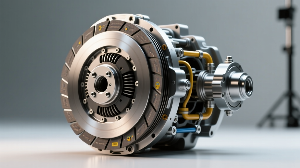
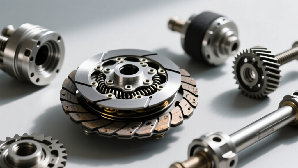
While the drivetrain and transmission clutches transfer engine torque to the wheels, the auto AC clutch serves a equally critical role in managing accessory drive loads and refrigerant compression. As we move through 2026, the automotive landscape features a mix of legacy fixed-displacement compressors and modern variable-displacement units. However, millions of vehicles on the road still rely on the traditional electromagnetic friction clutch assembly to engage and disengage the air conditioning compressor. Diagnosing an auto AC clutch requires the same methodical, symptom-based approach used in transmission diagnostics: isolating noise, analyzing vibration, and verifying mechanical 'feel' and electrical resistance.
This step-by-step guide will walk you through the precise diagnostic procedures for identifying auto AC clutch failures, complete with OEM specifications, air gap tolerances, and torque values for common compressor platforms like the Denso 10S17C and Sanden SD7V16.
Step 1: Diagnosing by Noise (Squeal, Grind, and Click)
Noise is the most common customer complaint regarding the auto AC clutch. However, misdiagnosing the source of the noise often leads to unnecessary compressor replacement. You must isolate whether the noise originates from the clutch friction surfaces, the pulley bearing, or the internal compressor swashplate.
The Squeal: Friction Surface Slippage
A high-pitched squeal upon initial engagement—or during high-head-pressure conditions—indicates that the clutch friction plate is slipping against the pulley rotor. This is rarely a failure of the friction material itself; rather, it is a symptom of an excessive air gap or a weak electromagnetic coil. When the air gap exceeds 0.040 inches (1.0 mm), the magnetic flux density is insufficient to lock the hub to the rotor, resulting in kinetic friction and severe squealing.
The Grind: Pulley Bearing Failure
If the noise is present only when the AC is turned OFF (clutch disengaged), the auto AC clutch pulley bearing is failing. The pulley rides on a sealed, double-row angular contact bearing. When the grease degrades or the bearing cage fractures, it produces a metallic grinding or growling noise that correlates with engine RPM. Use a mechanic's stethoscope with the probe placed on the compressor front head (away from the clutch) to amplify the bearing noise and confirm the diagnosis.
The Rapid Click: Coil or Relay Starvation
A rapid 'click-click-click' from the engine bay means the clutch is attempting to engage but immediately dropping out. This is typically caused by a high-resistance fault in the clutch relay, a failing low-pressure cutoff switch, or an internal break in the coil winding that manifests only when the copper expands under heat.
Step 2: Diagnosing by Vibration and Harmonic Chatter
Vibration in the auto AC clutch assembly can transfer through the accessory drive belt, causing harmonic chatter that mimics a failing alternator or tensioner.
Hub Runout and Wobble
With the engine off, grasp the clutch friction hub (the frontmost plate) and attempt to rock it laterally. Any perceptible play indicates wear in the hub splines or a failing pulley bearing. Once the engine is running and the clutch is engaged, observe the hub. Excessive axial wobble (runout exceeding 0.015 inches) points to a bent friction plate or a damaged compressor front shaft seal surface. This wobble causes cyclic belt slippage, which the tensioner cannot dampen, resulting in a low-frequency vibration felt in the steering wheel at idle.
Thermal Warping
If the clutch has been slipping for an extended period, the extreme heat (often exceeding 400°F at the friction surface) will thermally warp the steel rotor and friction plate. This warping creates a 'pulsing' vibration when engaged. A magnetic dial indicator mounted to the compressor housing will quickly reveal lateral runout caused by thermal warping.
Step 3: Diagnosing by 'Feel' and Electrical Measurement
The most definitive auto AC clutch diagnosis relies on physical measurements and electrical testing. 'Feel' in this context refers to the mechanical resistance and the precise measurement of the air gap.
Measuring the Air Gap
The air gap is the distance between the pulley rotor and the friction hub. This is the single most critical mechanical specification for the auto AC clutch.
- Target Specification: 0.020 to 0.030 inches (0.50 to 0.75 mm).
- Wear Limit: 0.040 inches (1.0 mm).
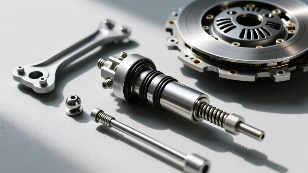
Use a tapered feeler gauge or a specialized clutch air gap tool. Insert the gauge between the rotor and the friction plate at three equidistant points. If the gap is too wide, the clutch will slip. If it is too tight (below 0.015 inches), the clutch may drag when disengaged, causing continuous compressor wear and parasitic engine drag. Correction involves removing the center bolt, pulling the hub, and removing or adding precision shims on the compressor shaft to adjust the gap.
Electrical Resistance and Voltage Drop
A 'feel' test for the electrical system requires a high-quality digital multimeter (such as a Fluke 87V). Disconnect the clutch coil connector and measure resistance across the coil terminals.
- Normal Resistance: 3.0 to 5.0 Ohms at 68°F (20°C).
- Shorted Coil: Below 2.5 Ohms (will blow the AC clutch fuse).
- Open Coil: Infinite / OL (internal winding break).
Furthermore, perform a voltage drop test across the clutch relay and wiring harness while the system is commanded ON. A voltage reading at the coil of less than 11.5 volts (with the engine running) indicates excessive resistance in the supply circuit, which will prevent the magnetic field from fully engaging the hub.
Diagnostic Matrix: Symptom to Solution
Use the following structured matrix to rapidly cross-reference your findings and determine the required corrective action for the auto AC clutch assembly.
| Primary Symptom | Diagnostic Test / Measurement | Probable Root Cause | Corrective Action |
|---|---|---|---|
| Squeal on Engagement | Air gap > 0.040" or Coil Voltage < 11.5V | Worn friction surfaces or voltage drop | Adjust shims to 0.025"; repair wiring harness |
| Grind (Clutch OFF) | Stethoscope on front head; lateral hub play | Pulley bearing cage failure | Press out old bearing, install new SKF/NTN bearing |
| Rapid Clicking | Coil resistance reads > 6.0 Ohms or OL | Thermal coil failure or bad relay | Replace electromagnetic coil assembly and relay |
| Harmonic Belt Chatter | Dial indicator shows > 0.015" lateral runout | Thermally warped rotor or bent hub | Replace complete clutch assembly (Rotor + Hub) |
Step-by-Step Replacement and Torque Specifications
When diagnosis dictates that the auto AC clutch must be replaced or rebuilt, adhering to precise torque specifications is vital to prevent catastrophic compressor shaft failure. The compressor shaft is supported by a front ceramic or steel bearing; over-torquing the center hub bolt will preload this bearing and cause premature destruction.
Common Compressor Torque Specs (2026 Reference)
- Denso 10S17C / 10PA17C: Hub center bolt torque is strictly 10 to 12 Nm (89 to 106 lb-in). Do not exceed 12 Nm.
- Sanden SD7V16 / PXE16: Hub center bolt torque is 15 to 20 Nm (11 to 15 lb-ft).
- Harrison / Delphi HT6 / V5: Hub center bolt torque is 18 to 24 Nm (13 to 18 lb-ft).
Coil and Snap-Ring Installation
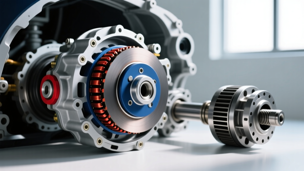
When replacing the electromagnetic coil, ensure the wire routing aligns with the compressor's relief notch to prevent the rotor from pinching the harness. The coil retaining snap-ring must be fully seated in its groove with the beveled edge facing outward (toward the pulley). Failure to seat the snap-ring properly will allow the coil to shift under magnetic load, instantly destroying the pulley bearing and snapping the coil wires.
Expert Insights for Modern Variable-Displacement Systems
It is crucial to note that many late-model vehicles (2018-2026) utilizing R-1234yf refrigerant feature variable-displacement compressors with an internal electronic control valve (ECV). Some of these systems use a 'limp-home' or complete disengagement clutch, while others are completely clutchless. If you are diagnosing a system that appears to have a locked auto AC clutch but the compressor is not pumping, the fault often lies in the internal ECV or the PWM signal from the HVAC module, not the mechanical clutch itself. Always verify the clutch type and control strategy via OEM service data before condemning the mechanical assembly.
For further technical standards on mobile air conditioning systems and electromagnetic clutch testing protocols, refer to the guidelines published by the Mobile Air Climate Systems Association (MACS). Additionally, comprehensive diagnostic flowcharts for specific Denso compressor platforms can be found in the Denso Automotive technical service bulletins. Proper diagnosis of the auto AC clutch relies on systematic elimination—trust your measurements, respect the torque specs, and verify the electrical supply before replacing mechanical components.