The Architecture of the Mating Surface
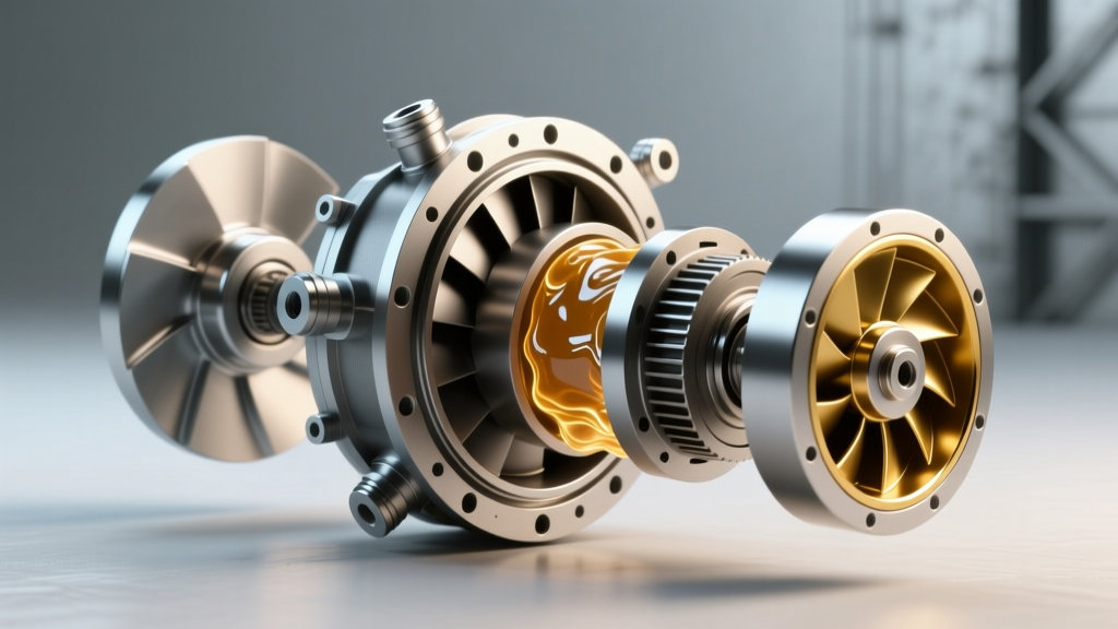
The mating interface between the engine flexplate and the Allison transmission torque converter represents one of the most highly stressed mechanical junctions in modern heavy-duty and commercial drivetrains. Unlike passenger vehicles that operate under relatively predictable load profiles, Allison-equipped platforms—ranging from the GM 6.6L Duramax-backed 1000 series to the massive 4000 series found in commercial refuse and transit buses—must endure extreme torsional vibration, high-stall torque multiplication, and severe thermal cycling. Understanding the exact bolt pattern, pilot clearance, and fitment tolerances is not merely an exercise in assembly; it is the primary defense against catastrophic front-pump failure, flexplate fatigue, and torque converter clutch (TCC) degradation.
In this technical deep-dive, we will dissect the geometry of the Allison transmission torque converter bolt pattern, outline precise measurement protocols for pump seating, and detail the exact torque specifications required to maintain drivetrain integrity in 2026 and beyond.
Decoding SAE Standards and Bolt Circle Geometry
Allison Transmission designs its torque converters to interface with engine flywheels and flexplates governed by SAE J617 standards. This standardization ensures that an Allison 3000 series can mate seamlessly to a Cummins ISB or a Caterpillar C7, provided the correct SAE bell housing and flywheel configuration are utilized. However, the light-duty 1000 series (predominantly paired with GM V8 engines) utilizes a proprietary GM-to-Allison hybrid bolt circle that deviates from traditional heavy-duty SAE norms.
The bolt circle diameter (BCD) dictates the leverage point of the engine's rotational mass. A larger BCD distributes the shear load across a wider area, reducing the stress concentration at individual fastener holes. When retrofitting or rebuilding, verifying the BCD is critical; attempting to force a mismatched flexplate using adapter rings or elongated holes will guarantee harmonic failure within the first 5,000 miles.
Series-Specific Fitment Data Matrix
| Allison Series | Typical Application | Bolt Circle / Pattern | Bolt Count | Pilot Hub Diameter | OEM Fastener Spec |
|---|---|---|---|---|---|
| 1000 / 2000 | GM 6.6L Duramax, Medium Duty | 12.375" (314.35mm) | 6 | 1.375" (34.9mm) | M10 x 1.5 (Grade 10.9) |
| 2500 / 3000 | Commercial, Motorhome, ISB/C7 | SAE #2 / #3 Housing | 6 or 8 | 1.75" - 2.00" | M12 x 1.75 or 1/2"-13 UNC |
| 4000 / 5000 | Heavy Duty, Transit, Refuse | SAE #1 / #0 Housing | 8 or 12 | 2.25"+ (57mm+) | M14 x 2.0 or 5/8"-11 UNC |
The 'Three Drops' Rule and Pump Seating Tolerances
The most common and destructive error made during the installation of an Allison transmission torque converter is failing to fully seat the converter hub into the transmission's front oil pump drive gear and stator support. The torque converter must engage three distinct internal components during installation:
- The Turbine Spline: Mating with the transmission input shaft.
- The Stator Support: Sliding over the one-way clutch assembly and stator shaft.
- The Oil Pump Drive Gear: Engaging the internal or external tangs that drive the front hydraulic pump.
Experienced Allison technicians refer to the 'Three Drops' or 'Three Clunks'—the tactile and audible feedback felt as the converter slides past each of these components. If the converter is only partially seated (e.g., resting on the pump gear but not fully engaged), the flexplate will act as a pry bar when the bell housing bolts are torqued down. This pulls the converter hub forward, instantly cracking the cast-aluminum pump housing or shearing the pump drive tangs upon initial engine startup.
Measuring Converter Recess Depth
Before mating the engine to the transmission, you must verify the converter is fully seated. Place a precision machined straight-edge across the transmission bell housing mating surface. Using digital calipers, measure the distance from the straight-edge to the flexplate mounting pad on the torque converter. For the Allison 1000/2000 series, this recess depth typically measures between 0.625" and 0.750" (15.8mm - 19.0mm). If the measurement is less than 0.500", the converter is not seated in the pump gear. Remove the converter, apply a light coat of assembly lubricant to the hub, and reinstall while rotating counter-clockwise until the final 'clunk' is felt.
Fastener Metallurgy and Torque Sequences
The fasteners securing the flexplate to the torque converter are subjected to immense cyclic loading. In high-torque diesel applications, the torsional pulses generated by the engine's combustion events can exceed 800 lb-ft of instantaneous rotational force at the converter pad. Using standard hardware store bolts or reusing stretched OEM fasteners is a recipe for disaster.
For aftermarket upgrades or heavy-duty rebuilds, we recommend upgrading to ARP (Automotive Racing Products) flexplate bolt kits, such as the ARP 234-7303 (for GM/Allison 1000 applications), which utilizes 8740 chrome-moly steel heat-treated to 200,000 psi tensile strength.
Official Torque Specifications & Thread Locker
- M10 x 1.5 (Allison 1000/2000): Torque to 45 - 50 lb-ft (61 - 68 Nm). Must be coated with a high-strength threadlocker (e.g., Loctite 262 or 271) to prevent backing out under diesel harmonics.
- M12 x 1.75 (Allison 3000 Series): Torque to 85 - 95 lb-ft (115 - 129 Nm). Apply medium-to-high strength threadlocker.
- 1/2"-13 UNC (SAE Heavy Duty): Torque to 90 - 100 lb-ft (122 - 135 Nm).
Note: Always torque the bolts in a star-pattern sequence, gradually stepping up the torque in three passes (e.g., 20 lb-ft, 35 lb-ft, final 50 lb-ft) to ensure even clamping load and prevent flexplate warping.
Diagnostic Symptoms of Fitment and Bolt Pattern Failures
When the bolt pattern is mismatched, the fasteners are under-torqued, or the pilot clearance is incorrect, the drivetrain will exhibit specific, often misdiagnosed symptoms. Recognizing these tc-symptoms early can save the transmission from total hydraulic failure.
1. Flexplate Cracking and Harmonic Resonance
If the torque converter pilot hub does not perfectly center within the flexplate bore, or if the bolts are torqued unevenly, the flexplate will operate under a state of constant bending stress. This manifests as a rhythmic 'knocking' or 'clunking' noise at idle (typically 600-800 RPM) that speeds up with engine RPM. Upon inspection, you will find microscopic stress fractures radiating outward from the bolt holes or the center crankshaft hub. In tuned Duramax applications, inadequate aftermarket flexplates combined with aggressive TCC lockup strategies frequently result in the flexplate breaking into two pieces, dropping the torque converter into the bell housing.
2. Torque Converter Clutch (TCC) Shudder and Slip Codes
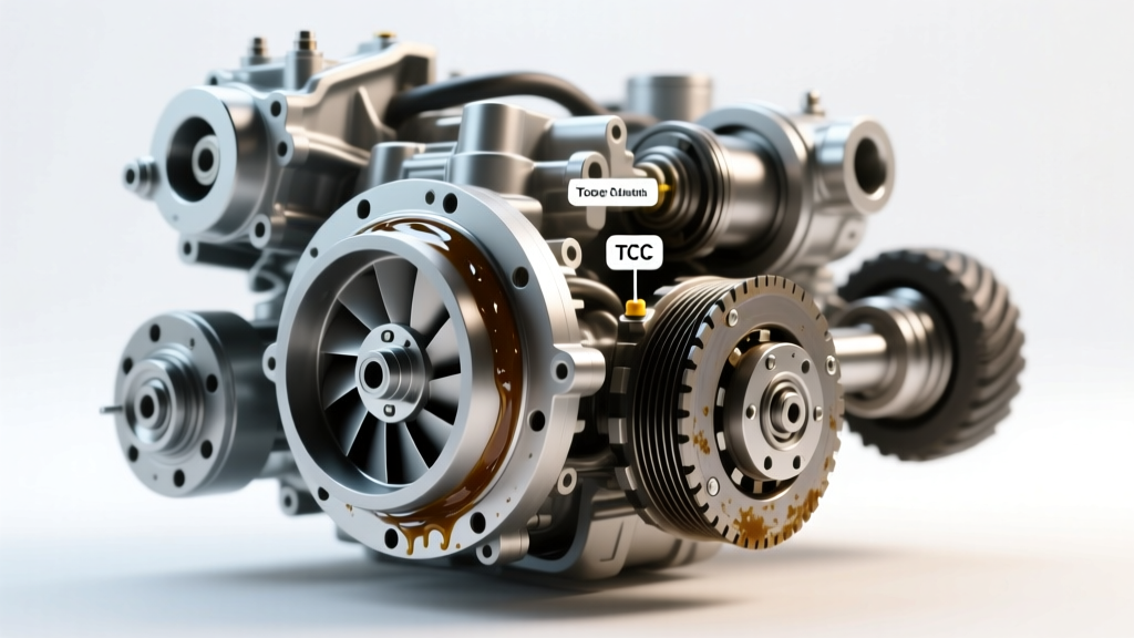
Improper fitment or a warped flexplate alters the axial position of the torque converter relative to the transmission case. This changes the internal endplay and the hydraulic fluid volume required to apply the TCC piston. Symptoms include a violent shudder between 1200 and 1500 RPM during light-throttle lockup, accompanied by diagnostic trouble codes (DTCs) such as:
- P0741: Torque Converter Clutch System Stuck Off / Excessive Slip
- P0742: Torque Converter Clutch System Stuck On
- P0711 / P0716: Transmission Fluid Temperature / Input Speed Sensor erratic readings (caused by front-pump cavitation due to a misaligned converter hub).
3. Front Seal Leakage and Pump Whine
If the converter hub is gouged, or if the pilot clearance is too tight (less than 0.010" radial clearance), the torque converter will exert lateral force on the front pump bushing. This wears the bushing prematurely, allowing high-pressure hydraulic fluid to bypass the front seal. You will notice ATF weeping from the bell housing inspection cover, accompanied by a high-pitched hydraulic whine that correlates with engine speed, not vehicle speed.
Flexplate Runout Verification Protocol
Before installing any Allison transmission torque converter, checking flexplate runout is a mandatory step often skipped by general repair shops. Mount a magnetic dial indicator to the engine block or transmission bell housing, positioning the probe against the outer edge of the flexplate ring gear or the converter mounting pad surface.
Rotate the crankshaft two full revolutions. According to Allison Transmission service guidelines and general SAE tolerances, total indicated runout (TIR) must not exceed 0.010" (0.25mm). If runout exceeds 0.015", the flexplate must be replaced, or the engine crankshaft flange must be inspected for debris, warping, or improper machining. Installing a new torque converter against a warped flexplate will transfer that runout directly into the converter cover, leading to immediate TCC friction material delamination.
Expert Technician Note: Never use an impact wrench to seat or remove torque converter-to-flexplate bolts. The sudden torsional shock can damage the internal turbine fins or the brazed joints of the stator assembly. Always use a calibrated torque wrench and a flywheel holding tool to secure the crankshaft during tightening or removal.
Summary and Preventative Maintenance
The longevity of an Allison-equipped drivetrain is inextricably linked to the precision of its torque converter fitment. By adhering strictly to SAE bolt circle specifications, verifying pump seating depth with calipers, utilizing high-tensile fasteners with appropriate threadlockers, and rigorously checking flexplate runout, technicians and enthusiasts can eliminate the root causes of premature converter and pump failures. Whether you are rebuilding a commercial 4000 series or upgrading a 1000 series for heavy towing, treating the bolt pattern and mating surface with engineering-level precision is the only path to reliable power transfer.