The Magic of Fluid Coupling: A Beginner's Guide
If you have ever wondered how an automatic transmission allows your car to come to a complete stop while the engine keeps running without stalling, the answer lies inside a donut-shaped component bolted to the engine's flexplate: the torque converter. For beginners, the easiest way to understand this component is to imagine two electric fans facing each other. If you turn one fan on (the engine), the air it blows will eventually cause the blades of the second, unplugged fan (the transmission input) to spin. In an automotive application, we replace the air with automatic transmission fluid (ATF). This hydrodynamic principle is the foundation of how your vehicle moves, but it is also the root cause of a very specific and destructive issue: torque converter slippage.
The Big Three: Impeller, Turbine, and Stator
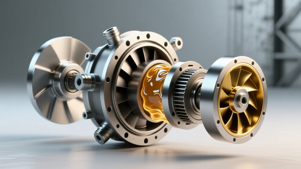
To understand why slippage happens, you must first understand the internal architecture. A torque converter is not an empty shell; it is a precisely engineered hydraulic pump and motor combined into one unit.
- The Impeller (Pump): Bolted directly to the converter housing, the impeller spins at engine RPM. Its curved fins grab ATF and violently fling it outward via centrifugal force.
- The Turbine: Connected to the transmission's input shaft, the turbine sits directly across from the impeller. The ATF thrown by the impeller strikes the turbine's fins, transferring rotational energy and turning the transmission gears.
- The Stator: Sitting in the center between the impeller and turbine, the stator is mounted on a one-way clutch. Its job is to redirect the fluid returning from the turbine back into the impeller, effectively multiplying torque (up to 2.5x) during hard acceleration from a stop.
When Good Physics Go Bad: What is Torque Converter Slippage?
By definition, a fluid coupling inherently experiences slip. When your car is idling in gear at a red light, the impeller is spinning, but the turbine is held stationary by the brakes. This is normal hydrodynamic slip. However, when automotive technicians and drivers talk about torque converter slippage as a symptom or failure, they are referring to abnormal slip—specifically, the failure of the internal lockup mechanism or the degradation of the internal fins.
Abnormal slippage generates massive amounts of friction and heat. ATF temperatures can quickly exceed 250°F (121°C), cooking the fluid, destroying the varnish on the transmission's internal clutch packs, and ultimately leading to catastrophic transmission failure.
| Parameter | Normal Hydrodynamic Slip | Abnormal Torque Converter Slippage |
|---|---|---|
| Operating Condition | Idle, initial take-off, heavy throttle | Cruising at steady highway speeds (45+ MPH) |
| RPM Differential | 300 - 1500+ RPM (Impeller vs Turbine) | > 100 RPM when TCC is commanded LOCKED |
| Fluid Temp Impact | Managed by transmission cooler | Rapid spike > 230°F, flashing temp warnings |
| Driver Sensation | Smooth, seamless acceleration | RPM flaring, shudder, sluggish acceleration |
The Torque Converter Clutch (TCC) Lockup Mechanism
To eliminate the parasitic power loss and fuel economy penalty caused by constant fluid slip, engineers introduced the Torque Converter Clutch (TCC). When your vehicle reaches cruising speed (usually between 35 and 50 MPH), the Transmission Control Module (TCM) commands a solenoid to route hydraulic pressure to the front of the torque converter. This pressure clamps a large friction disc against the inside of the converter cover, physically locking the engine to the transmission input shaft. At this point, it operates exactly like a manual transmission clutch—creating a 1:1 mechanical connection with zero slip.
When torque converter slippage occurs at highway speeds, it means this mechanical lock is failing. The friction material is worn, the hydraulic apply circuit is leaking, or the TCC Pulse Width Modulation (PWM) solenoid is failing to regulate pressure.
Real-World Transmission Examples
- GM 4L60E / 4L80E: Notorious for TCC apply valve bore wear in the aluminum valve body. Even if the torque converter itself is perfectly healthy, the worn valve bleeds off hydraulic pressure, preventing the TCC from fully locking. This results in P0741 codes and severe slippage. According to Sonnax technical resources, reaming the valve bore and installing a sleeved apply valve is the only permanent fix.
- ZF 8HP (8-Speed): Found in millions of modern BMW, Audi, and Dodge vehicles. The ZF 8HP utilizes a highly advanced carbon-fiber friction material for its TCC and operates with controlled micro-slip (around 10-20 RPM) even when 'locked' to dampen engine vibrations. As detailed in ZF's official drivetrain documentation, using the incorrect fluid (it requires specific ZF LifeguardFluid 8) will degrade the carbon friction lining, causing aggressive shudder and abnormal slippage.
- Ford 10R80 / GM 10L90: These modern 10-speed units use centrifugal pendulum absorbers and multi-stage lockup clutches. Slippage here is rarely a worn friction disc; it is almost always caused by contaminated fluid clogging the highly sensitive TCC regulator valves or failing turbine shaft seals.
Diagnostic Steps: Pinpointing the Slip
As of 2026, diagnosing torque converter slippage relies heavily on high-speed CAN bus PID logging rather than just 'seat-of-the-pants' feel. Here is the professional diagnostic workflow:
- Scan for TCC Slip Speed PID: Connect an advanced OBD2 scanner and graph the TCC Slip Speed parameter. Drive the vehicle at a steady 60 MPH in top gear on a flat road. The slip speed should read between -20 and +20 RPM. If you see sustained slip of 100+ RPM while the TCC Solenoid Duty Cycle reads 100% (or fully locked), you have confirmed abnormal slippage.
- Check Fluid Condition and Level:Pull the dipstick or check the level plug. If the fluid smells burnt or contains heavy metallic/glitter particulate, the internal stator one-way clutch or the TCC friction lining has physically disintegrated.
- Perform a Hydraulic Pressure Test: Install a transmission pressure gauge on the TCC apply port. If line pressure is high but TCC apply pressure drops when hot, you have an internal seal leak inside the torque converter or the transmission input shaft.
Expert Diagnostic Tip: Never perform a stall test on a modern ZF 8HP or Ford 10R80 transmission to check for slippage. These units are designed to unlock the TCC and utilize fluid coupling to protect the drivetrain. A traditional stall test will only yield inaccurate data and risk overheating the highly sensitive friction materials. Stick to OBD2 PID slip logging.
Replacement Costs and Part Considerations
If your diagnostic data confirms internal torque converter slippage that cannot be resolved by replacing a TCC solenoid or repairing the valve body, the torque converter must be replaced (and ideally, rebuilt by a specialist). Because the transmission must be dropped to access the converter, labor is the most significant expense.
| Transmission Model | OEM / High-Quality Reman Part Cost | Estimated Labor (R&R) | Total Shop Cost Range |
|---|---|---|---|
| GM 4L60E | $350 - $550 | $500 - $750 | $850 - $1,300 |
| ZF 8HP70 / 8HP90 | $800 - $1,300 | $900 - $1,400 | $1,700 - $2,700 |
| Ford 10R80 | $650 - $950 | $800 - $1,200 | $1,450 - $2,150 |
Note: Prices reflect 2026 average independent shop rates. Dealership pricing will typically be 30-50% higher due to OEM-only parts mandates and elevated hourly labor rates.
Summary
Understanding how a torque converter works is the first step in recognizing when it is failing. While fluid slip is a normal part of getting your vehicle moving from a dead stop, torque converter slippage at cruising speeds is a critical failure of the TCC lockup mechanism. Whether it is a worn friction disc in a ZF 8HP, a leaking turbine shaft seal in a 10R80, or a worn valve body bore in a 4L60E, ignoring the symptoms will inevitably lead to a complete transmission rebuild. Monitor your TCC slip RPMs, maintain your ATF with the exact OEM-specified fluid, and address shudder or RPM flaring immediately to save your drivetrain.
For further reading on transmission hydraulic circuits and torque converter diagnosis, the Automatic Transmission Rebuilders Association (ATRA) offers extensive technical bulletins that detail the intricate hydraulic pathways governing modern TCC apply systems.