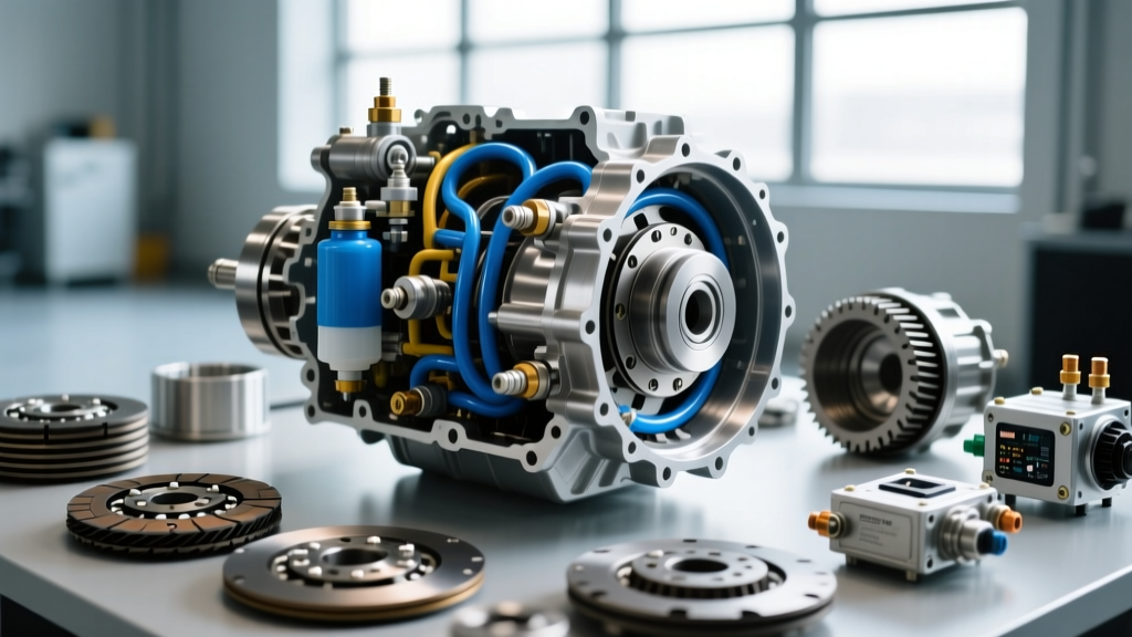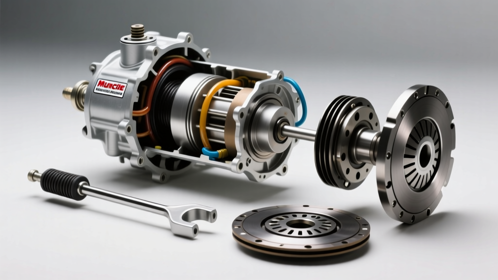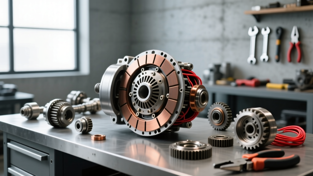
While AutoGearNexus primarily focuses on drivetrain and transmission friction clutches—such as the torque converter lock-up clutches in a ZF 8HP or the manual clutch discs in a Tremec T56—the modern vehicle relies on several critical auxiliary electromagnetic clutches. The most vital of these is the A/C compressor clutch. When this electromagnetic friction device fails, it mimics the symptoms of a slipping drivetrain clutch: loss of power transfer, excessive heat, and mechanical chatter. Because the compressor clutch is driven by the serpentine belt, a seized or slipping clutch can lead to catastrophic belt failure and engine overheating.
This technical deep-dive provides a comprehensive clutch system inspection checklist focused on the A/C compressor, detailing the exact electrical and mechanical procedures required to isolate faults. Whether you are dealing with a traditional cycling clutch on a Sanden SD7V16 or diagnosing an intermittent slip on a Denso ND-S series, understanding the electromagnetic principles at play is essential for accurate diagnostics.
The Electromagnetic Clutch System Inspection Checklist
Before connecting your diagnostic tools, perform a systematic physical and electrical inspection. This checklist ensures you do not misdiagnose a simple wiring fault as a failed internal coil.
| Inspection Phase | Component | Target Condition / Specification | Common Failure Mode |
|---|---|---|---|
| Visual | Friction Hub & Rotor | Clean, free of oil, no severe bluing | Glazing from refrigerant oil contamination |
| Visual | Serpentine Belt & Tensioner | Proper tension, no cracking | Slipping belt mimicking clutch slip |
| Electrical | Clutch Coil Connector | Tight fitment, no corrosion | High resistance causing voltage drop |
| Electrical | Clutch Relay (Underhood) | Clicks audibly, pins not burnt | Stuck open/closed, melted sockets |
| Mechanical | Air Gap (Hub to Rotor) | 0.020" - 0.030" (0.5mm - 0.75mm) | Wear increases gap, preventing engagement |
| Mechanical | Compressor Shaft Bearing | Smooth rotation, no axial play | Seized bearing melts clutch coil |
How to Test AC Compressor Clutch With Multimeter: Core Procedures
To accurately diagnose the electromagnetic circuit, you must isolate the clutch coil from the vehicle's wiring harness. Set your digital multimeter (DMM) to the appropriate scales as outlined below.
Phase 1: Coil Resistance and Continuity Testing
Disconnect the electrical connector at the compressor clutch. Set your multimeter to the Ohms (Ω) scale, typically the 200Ω setting. Place one probe on the clutch coil's positive terminal and the other on the negative terminal (or ground, if it is a single-wire coil that grounds through the compressor housing).
- Normal Reading: Most 12V automotive A/C clutch coils (such as those on Harrison HT6 or Sanden compressors) should read between 3.0 and 5.0 ohms at room temperature (68°F / 20°C).
- Open Circuit (OL):strong> If the multimeter reads 'OL' or infinite resistance, the internal copper windings are broken. The coil is dead and must be replaced.
- Short Circuit (Near 0Ω):strong> If the resistance is below 2.0 ohms, the coil has an internal short. This will draw excessive amperage, potentially melting the wiring harness or blowing the HVAC fuse.
Phase 2: Voltage Drop and Circuit Integrity
A healthy coil will not engage if it is not receiving adequate voltage. Reconnect the harness and back-probe the connector with the engine running and the A/C set to maximum cooling.
- Voltage Supply: You should read a minimum of 11.5V DC at the clutch connector. If you read battery voltage at the underhood relay but only 9.0V at the compressor, you have a severe voltage drop in the wiring harness or a corroded ground point.
- Ground Verification: For single-wire clutches, set the DMM to DC Volts. Place the positive probe on the battery positive terminal and the negative probe on the compressor housing. A reading above 0.1V indicates a poor engine-to-chassis ground, which starves the clutch coil of the amperage required to generate a strong magnetic field.
Advanced Diagnostics: PWM Clutches vs. Traditional Cycling Clutches
It is critical to identify which type of clutch system your vehicle utilizes before testing. Traditional systems use a simple on/off cycling clutch controlled by a standard 12V relay. However, many modern vehicles (particularly those with variable displacement compressors like the Denso ND-S series) utilize a Pulse Width Modulated (PWM) clutch or an electronic control valve.
PWM clutches do not receive a steady 12V. Instead, the Powertrain Control Module (PCM) rapidly pulses the ground circuit to modulate the magnetic field strength, allowing the clutch to slip intentionally and control compressor output. If you test a PWM clutch with a standard multimeter, you may see fluctuating voltage readings (e.g., jumping between 4V and 11V) and mistakenly diagnose a bad connection. For PWM circuits, an oscilloscope is required to read the duty cycle waveform. According to the Mobile Air Climate Systems Association (MACS), misdiagnosing a PWM signal as a failing relay is one of the most common errors in modern HVAC diagnostics.
Mechanical Verification: Air Gap and Friction Surface Analysis
Electrical perfection means nothing if the mechanical air gap is out of specification. The magnetic field strength drops exponentially as the distance between the rotor and the friction hub increases.
Expert Tech Tip: Never use a screwdriver to pry the clutch hub off the compressor shaft. The internal snap rings and shaft threads are easily damaged. Always use a dedicated clutch hub puller tool (e.g., Lisle 45750 or OEM Tools 27113) to apply even, axial force.
Using a feeler gauge, measure the gap between the friction plate and the rotor pulley at three equidistant points. The specification for nearly all modern automotive compressors is 0.020" to 0.030" (0.5mm to 0.75mm). If the gap exceeds 0.040", the electromagnet cannot pull the hub across the gap, resulting in a 'clicking' sound as the hub rapidly engages and disengages (chatter). To fix this, remove the hub, take out one of the internal shim washers, and re-measure. Conversely, if the gap is below 0.015", the clutch may drag when disengaged, causing the friction surface to overheat and glaze.
Thermal Breakdown: The Hidden Cause of Intermittent Slippage
One of the most frustrating symptoms in clutch system diagnostics is an A/C system that blows ice-cold for the first twenty minutes of a drive, then suddenly stops cooling in heavy traffic. This is a classic sign of thermal coil breakdown.
Copper wire exhibits a positive temperature coefficient, meaning its electrical resistance increases as it gets hotter. A clutch coil that reads a perfectly healthy 4.0 ohms when cold in the garage may swell to 7.5 ohms when exposed to 220°F under-hood temperatures in stop-and-go traffic. As resistance climbs, amperage drops (Ohm's Law: I = V/R). The weakened magnetic field can no longer hold the friction hub against the rotor, and the clutch slips. AA1Car Automotive AC Diagnostics recommends testing coil resistance immediately after the vehicle has been driven and the symptom has manifested, rather than testing a cold component in the service bay.
Repair Economics: Component Costs and Torque Specifications
When the clutch system inspection checklist confirms a failure, you have several repair pathways. Replacing the entire compressor is often unnecessary if the internal shaft and swash plate are healthy.
- Clutch Coil Assembly: $45 to $120 (Parts). Requires refrigerant recovery if the coil is integrated into the front head, but many can be swapped with snap-ring pliers without evacuating the system.
- Friction Hub and Pulley Bearing: $60 to $150 (Parts). The pulley bearing is a common failure point; if it seizes, it will melt the coil and shear the hub.
- Complete Compressor Assembly: $250 to $800+ (Parts). Required if the internal shaft seal is leaking refrigerant oil onto the clutch friction surfaces.
Crucial Torque Specifications: When reinstalling the clutch hub, the center retaining bolt must be torqued precisely. For most M8x1.25 center bolts (common on Sanden and Delphi compressors), the torque spec is 15 to 20 Nm (11 to 15 lb-ft). For larger M10 bolts found on heavy-duty truck compressors, the spec is typically 25 to 30 Nm (18 to 22 lb-ft). Always use a threadlocker (such as Loctite 243) on the center bolt, as the rotational inertia of the clutch engagement will easily back out an untreated bolt, leading to catastrophic hub ejection. For comprehensive parts sourcing and torque charts, resources like ACKits Automotive Air Conditioning provide excellent OEM cross-reference data.
By treating the A/C compressor clutch with the same diagnostic rigor as a transmission friction pack, you eliminate guesswork, prevent repeat failures, and restore optimal cabin cooling performance.