Understanding the Electromagnetic Clutch: Drag vs. Release Failures
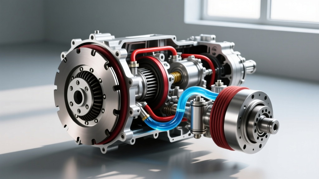
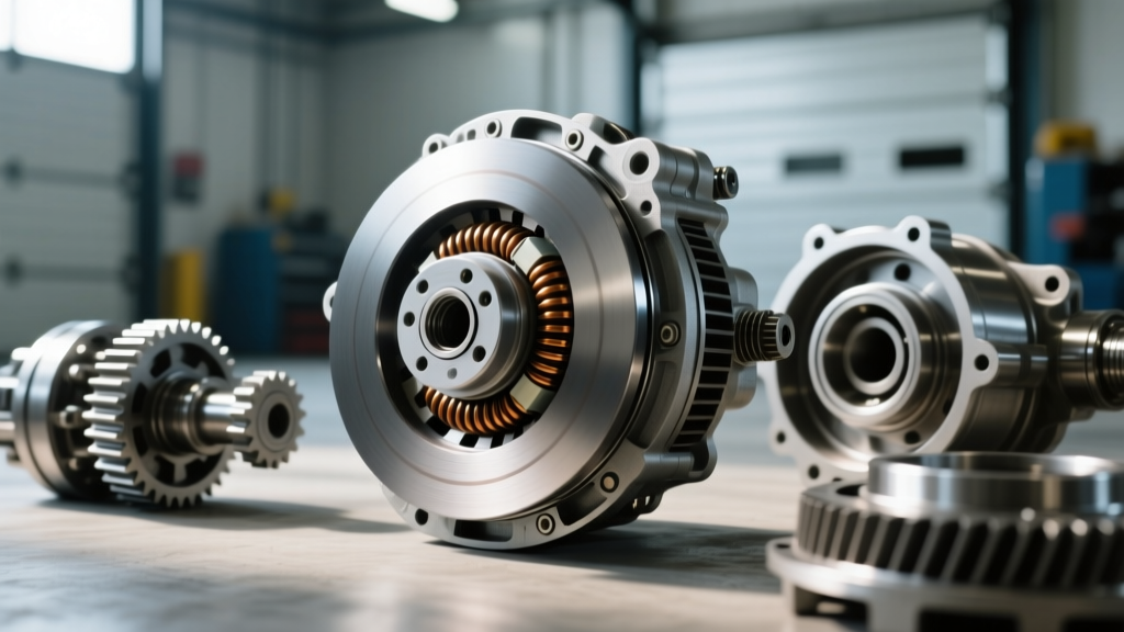
While automotive enthusiasts often associate the word 'clutch' with manual transmission drivetrains, the auto AC compressor clutch is a critical electromagnetic friction device that dictates your vehicle's climate control performance. Unlike a hydraulic drivetrain clutch, the AC compressor clutch relies on a magnetic field to bridge a precise air gap, locking the drive pulley to the compressor's internal shaft. When this system fails, it typically manifests in two distinct ways: clutch drag (failure to disengage) or release problems (failure to engage or severe slipping).
In 2026, while many modern EVs and newer passenger vehicles utilize clutchless variable-displacement compressors, millions of internal combustion vehicles, heavy-duty trucks, and agricultural platforms still rely on traditional electromagnetic clutch assemblies. Diagnosing these systems requires a methodical approach, blending electrical diagnostics with precision mechanical measurements. This step-by-step guide will walk you through identifying, measuring, and resolving AC compressor clutch drag and release issues.
Symptom Breakdown: Drag vs. Release
- Clutch Drag (Failure to Disengage): The clutch friction plate remains bound to the pulley even when the AC is turned off. This causes continuous compressor operation, leading to evaporator freezing, excessive engine parasitic drag, and premature pulley bearing failure due to constant heat buildup.
- Release Problems (Failure to Engage / Slipping): The clutch fails to pull in when commanded, or it engages but slips under high system head pressure. Symptoms include no cabin cooling, a loud squealing or chirping noise from the engine bay, and a blued or glazed friction plate caused by extreme friction heat.
Required Tools and Safety Equipment
Before beginning the diagnostic process, gather the following tools to ensure accurate measurements and safe component handling:
- Digital Multimeter (DMM) with millivolt and ohm settings
- Feeler gauge set (Metric and SAE)
- Dial indicator with a magnetic base (for measuring pulley runout)
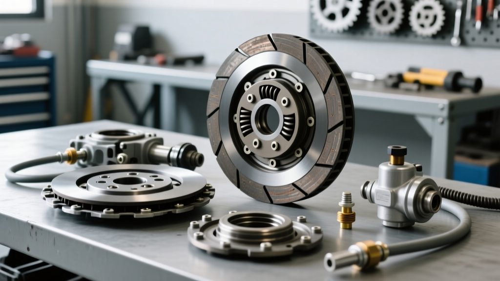
- AC clutch puller and installer tool set (specific to your compressor model)
- Inch-pound torque wrench
- Safety glasses and nitrile gloves
Step 1: Electrical Diagnostics for Release Problems
If your clutch is failing to engage or is slipping, the first suspect is always the electrical circuit. The electromagnetic coil requires sufficient amperage to generate the magnetic force necessary to pull the friction plate across the air gap.
1.1 Voltage Drop Testing
With the engine running and the AC set to maximum cooling, back-probe the clutch electrical connector using your DMM. You must read a minimum of 11.5 volts at the clutch pigtail. If you read battery voltage at the under-hood fuse box but only 9.5V at the clutch connector, you have a voltage drop issue in the wiring harness, a failing AC compressor relay, or a corroded ground circuit. The clutch coil cannot generate adequate magnetic force on low voltage, resulting in a 'release' or slipping failure.
1.2 Coil Resistance Verification
Disconnect the electrical connector and set your multimeter to measure Ohms (Ω). Place the probes across the two terminals of the clutch coil (or the single terminal and ground, if it's a grounded-coil design). A healthy auto AC compressor clutch coil typically reads between 3.0 and 5.0 ohms at 68°F (20°C). If the meter reads 'OL' (Open Line), the internal windings are broken. If it reads near 0.0 ohms, the coil has an internal short and will blow your AC fuse upon engagement.
Step 2: Diagnosing Mechanical Drag and Binding
If the clutch drags (spins the compressor shaft when the AC is turned off), the issue is mechanical or magnetic. First, rule out a welded relay in the fuse box by unplugging the clutch connector entirely. If the clutch still spins with the pulley when unplugged, the drag is localized to the compressor nose.
2.1 Inspecting for Residual Magnetism and Warping
Over time, the electromagnetic coil can develop residual magnetism, or the friction surfaces can warp due to severe slipping events. Inspect the mating surfaces of the pulley and the clutch hub. If you see deep scoring, bluing (heat marks), or transferred friction material, the physical tolerance has been compromised. Furthermore, check the pulley bearing. Grab the pulley (with the belt removed) and attempt to wobble it. Any radial play indicates a failing bearing that may be pushing the pulley out of alignment, causing the clutch plate to drag against it mechanically.
Step 3: Measuring and Adjusting the Air Gap
The air gap is the single most critical mechanical specification for an auto AC compressor clutch. It is the physical distance between the pulley's friction ring and the clutch hub's friction plate.
- Gap Too Wide (>0.040 inches): The magnetic field cannot bridge the distance. The clutch will fail to engage, or it will slip violently under load, generating massive heat and destroying the friction surfaces.
- Gap Too Narrow (<0.015 inches): The clutch will drag when disengaged due to residual magnetism, minor pulley runout, or thermal expansion of the metal components.
Common Compressor Clutch Specifications
Refer to the table below for baseline specifications on the most common compressor platforms found in the global fleet. Always verify with OEM service manuals for your specific application.
| Compressor Model | Target Air Gap | Coil Resistance (at 68°F) | Hub Bolt Torque |
|---|---|---|---|
| Denso 10S17C / 10PA17C | 0.020' - 0.030' (0.5 - 0.75mm) | 3.2 - 4.2 Ohms | 10 - 12 Nm (7 - 9 lb-ft) |
| Sanden SD7B10 / SD5 | 0.016' - 0.028' (0.4 - 0.7mm) | 3.5 - 4.5 Ohms | 12 - 15 Nm (9 - 11 lb-ft) |
| GM Harrison HT6 / V5 | 0.020' - 0.035' (0.5 - 0.9mm) | 3.0 - 4.0 Ohms | 15 - 20 Nm (11 - 15 lb-ft) |
The Shimming Procedure
If your air gap is out of specification, you must adjust it using shims located on the compressor shaft beneath the clutch hub.
- Remove the Center Bolt: Use an impact wrench or a clutch holding spanner to remove the center retaining bolt. Note that some Sanden compressors use a left-hand thread (reverse thread) on the center bolt.
- Pull the Clutch Hub: Thread the appropriate clutch puller tool into the hub and slowly turn the forcing screw to pop the hub off the splined shaft. Do not pry with a screwdriver, as you will warp the friction plate.
- Adjust Shims: Inside the hub recess or on the shaft, you will find thin metal washers (shims). To decrease the air gap (fix a release/slipping problem), remove a shim. To increase the air gap (fix a drag problem), add a shim.
- Reassemble and Measure: Reinstall the hub and torque the center bolt to the manufacturer's specification (refer to the table above). Use your feeler gauges to measure the gap at three equidistant points around the circumference. The variance between the three points should not exceed 0.005 inches. If it does, the clutch hub is warped or the pulley bearing is failing.
Step 4: Component Replacement and Sourcing
If shimming does not resolve the issue, or if the friction surfaces are severely glazed and blued, component replacement is mandatory. In 2026, sourcing high-quality OEM or OEM-equivalent replacements is easier than ever, but avoiding cheap, unbranded aftermarket clones is critical for longevity.
According to technical documentation from Sanden's official automotive division, using inferior friction materials can lead to rapid degradation and catastrophic compressor lockup. When replacing the clutch assembly, it is highly recommended to replace the entire coil, pulley, and hub as a matched set to ensure consistent magnetic flux and friction coefficients.
For pricing and part sourcing, databases like RockAuto provide excellent cross-referencing for OEM part numbers. For example, a complete Denso-style clutch assembly (Part # 471-0105 equivalent) typically ranges from $85 to $140, while a standalone replacement coil (e.g., Four Seasons 47181) costs between $30 and $55. Always verify the pulley diameter and groove count (e.g., 6-groove serpentine vs. 4-groove V-belt) before ordering.
Final Verification Checklist
Before reinstalling the drive belt and recharging the system, complete this final verification checklist to ensure your auto AC compressor clutch drag and release problems are fully resolved:
- [ ] Air gap measures within 0.005' variance across three points.
- [ ] Center bolt torqued to exact OEM specification using an inch-pound torque wrench.
- [ ] Coil resistance verified between 3.0 and 5.0 ohms.
- [ ] Voltage at the clutch pigtail reads >11.5V with the engine running and AC commanded ON.
- [ ] Clutch disengages instantly when power is removed (no mechanical drag or residual spin).
- [ ] Pulley bearing exhibits zero radial or axial play when spun by hand.
By adhering to these precise electrical and mechanical tolerances, you will restore optimal climate control performance and protect the compressor's internal shaft seals from the destructive forces of misalignment and excessive heat.
For further reading on modern HVAC system diagnostics and compressor tear-down procedures, consult the technical service bulletins available via the Denso Aftermarket portal, which offers comprehensive PDF guides on identifying internal control valve failures that often mimic external clutch release problems in variable-displacement systems.