Understanding Clutch Drag and Release Problems in Modern Drivetrains
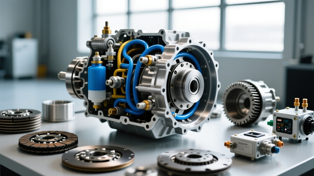
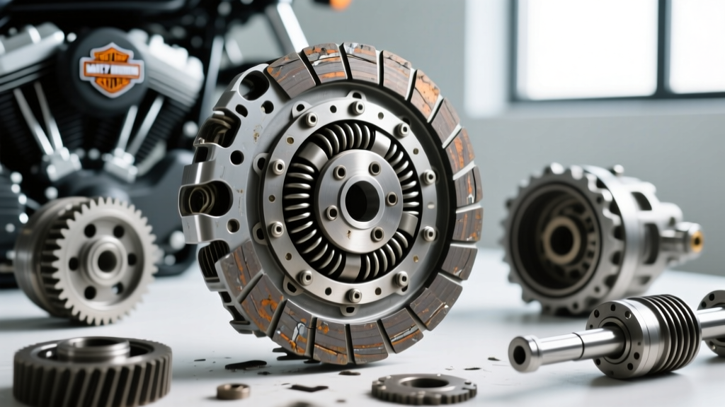
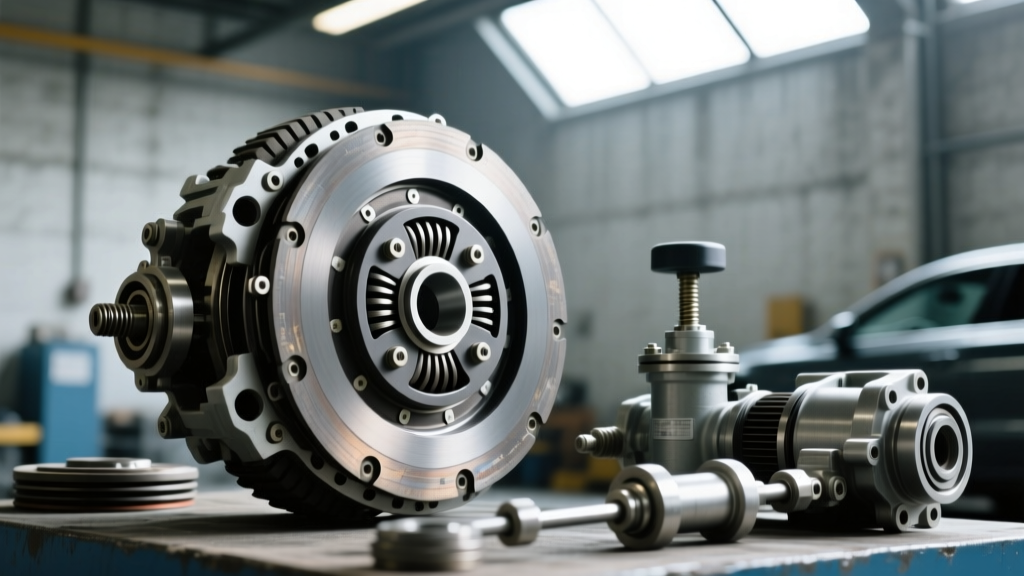
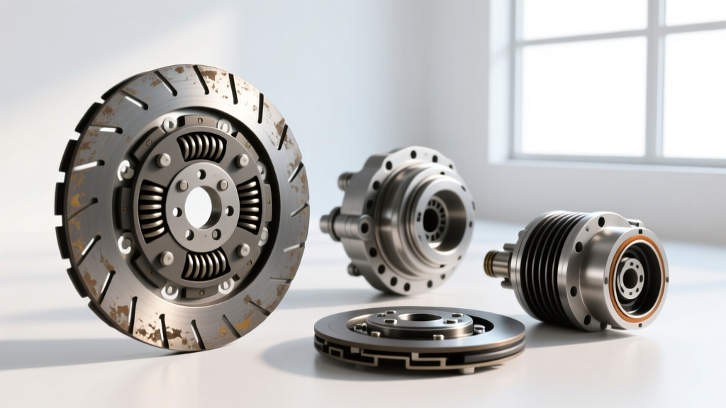
Clutch drag occurs when the friction disc fails to fully disengage from the flywheel, even when the clutch pedal is fully depressed. In high-torque applications like the Tremec T56 Magnum or the ZF S6-650 (found in heavy-duty diesel trucks), this symptom manifests as grinding during gear engagement, a pronounced forward creep at stoplights, and difficulty shifting into reverse. Traditional diagnostics immediately point to the hydraulic release system, the concentric slave cylinder (CSC), or a warped clutch disc.
However, as we navigate the 2026 automotive diagnostic landscape, master technicians recognize a critical edge case: parasitic accessory drag. When an accessory component seizes or creates immense rotational resistance, it alters engine deceleration dynamics and crankshaft endplay. This can mimic, exacerbate, or completely mask traditional transmission clutch release problems. The most common culprit? A failing air conditioning compressor clutch assembly.
The Anatomy of a Misdiagnosis
When you depress the clutch pedal, the engine is unloaded from the drivetrain. If the engine is fighting severe rotational drag from a binding AC compressor pulley bearing, the engine RPM will plummet erratically, and the harmonic balancer can experience micro-vibrations. To the driver, this feels exactly like clutch chatter or a failing release bearing. Before dropping a transmission and spending upwards of $1,200 to $2,500 on a clutch kit replacement, you must isolate the engine's accessory drive.
Diagnostic Matrix: Transmission Release vs. Accessory Drag
Use the following comparison chart to determine if your clutch drag and release problems stem from the drivetrain or the frontend accessory drive (FEAD).
| Symptom | Transmission Clutch Drag (Internal) | AC Compressor Clutch Seizure (Parasitic) |
|---|---|---|
| Pedal Feel | Spongy, or solid but failing to release | Normal hydraulic pressure, consistent feel |
| Engine RPM Behavior | Hangs or drops normally when unloaded | Lugs, stalls, or drops erratically at idle |
| Noise Profile | Scraping from the bellhousing (release bearing) | High-pitched whine or low rumble from the serpentine belt area |
| Belt Test | Symptoms persist with belt removed | Symptoms vanish when serpentine belt is removed |
Step-by-Step Guide: Changing AC Compressor Clutch to Eliminate Parasitic Drag
If removing the serpentine belt eliminates the clutch drag and engine lugging, the issue is isolated to the frontend. You do not need to evacuate the refrigerant system to replace just the clutch assembly. Here is the professional procedure for changing AC compressor clutch components to restore proper engine rotational freedom.
Required Tools and Specifications
- Clutch hub puller (specific to your compressor, e.g., Sanden SD7 or Denso 10S17C)
- Snap ring pliers (internal/external)
- Feeler gauge set (for air gap measurement)
- Torque wrench (inch-pounds)
- Replacement AC Clutch Kit (Coil, Pulley, Hub, and shim kit)
The Removal Procedure
- Remove the Center Hub Bolt: Locate the center bolt on the AC clutch friction plate. This is typically a 10mm or 12mm hex head. Use an impact wrench or a strap wrench to hold the pulley while breaking the bolt loose. Remove the bolt and washer.
- Extract the Friction Plate: Thread the clutch hub puller into the center of the friction plate. Tighten the puller's center screw against the compressor shaft until the plate pops free. Note the number and thickness of the shims located behind the plate. These are critical for the air gap.
- Remove the Pulley Snap Ring: Use snap ring pliers to remove the large C-clip securing the pulley bearing to the compressor snout.
- Pull the Pulley Assembly: Attach a standard 3-jaw puller to the pulley. Carefully press it off the compressor shaft. Inspect the shaft for rust or scoring.
- Remove the Electromagnetic Coil: Disconnect the wiring harness. Remove the snap ring holding the coil in place and slide the coil off the compressor housing.
The Installation and Air Gap Calibration
Proper air gap is the difference between a functioning AC system and a clutch that drags continuously, recreating your original problem. According to SAE International standards, most automotive AC clutches require an air gap between 0.020" and 0.030" (0.5mm - 0.75mm).
- Install the New Coil: Slide the new electromagnetic coil onto the compressor. Ensure the anti-rotation tab aligns with the housing notch. Secure with the snap ring.
- Press on the New Pulley: Using a bearing driver that only contacts the outer race of the pulley bearing, press the new pulley assembly onto the shaft. Install the snap ring.
- Shim the Friction Plate: Reinstall your saved shims (or use the ones provided in the kit) onto the compressor shaft. Slide the new friction plate on and hand-tighten the center bolt.
- Measure the Air Gap: Use a feeler gauge to measure the gap between the friction plate and the pulley face at three equidistant points. If the gap is too wide, remove a shim. If it is too tight (which will cause severe parasitic drag), add a shim.
- Final Torque: Torque the center bolt to the manufacturer's specification, typically between 11 and 15 lb-ft (15-20 Nm). Over-torquing can stretch the shaft and alter the air gap dynamically under load.
Addressing True Drivetrain Release Problems
If you have completed the AC clutch replacement, verified the serpentine belt is routing smoothly, and the manual transmission still exhibits clutch drag and release problems, the fault lies within the bellhousing or hydraulic circuit.
Hydraulic System and Concentric Slave Cylinders (CSC)
Modern manual transmissions, including the Tremec lineup and various Porsche transaxles, rely heavily on internal Concentric Slave Cylinders. A failing CSC will bypass fluid internally, preventing the necessary 0.450" to 0.550" of travel required to fully disengage a high-clamp-load pressure plate.
- Fluid Check: Verify the use of the correct fluid. While many older systems use DOT 3 or DOT 4, modern 2026 heavy-duty applications often require specific low-viscosity DOT 4 LV or DOT 5.1 to ensure rapid hydraulic response.
- Pressure Bleeding: Vacuum bleeding is often insufficient for CSCs located at the bottom of the bellhousing. Use a pressure bleeder set to 15-20 PSI to force fluid upward through the master cylinder and AN4 hydraulic lines, pushing trapped air out of the system.
Pivot Ball and Fork Wear
In external release systems, the clutch fork pivots on a hardened steel ball stud. Over 80,000 miles, the socket in the fork can wear oblong. This wear introduces a "lost motion" variable. Even if the slave cylinder is pushing a full 0.600", the worn pivot point may only translate 0.400" of movement to the release bearing. This results in incomplete disengagement and severe clutch drag.
The Fix: Remove the transmission and inspect the pivot ball. If the ball shows a concave wear groove, or the fork socket is polished and elongated, replace both components. Always apply a high-temperature molybdenum disulfide (moly) grease to the pivot point and the release bearing contact pad to prevent future wear and eliminate high-pitched squealing during clutch engagement.
Final Diagnostic Verification
Whether your clutch drag and release problems were caused by a seized AC compressor clutch bearing transferring parasitic load to the crankshaft, or a worn internal hydraulic slave cylinder, the verification process remains the same. With the vehicle safely on a lift, the engine running, and the wheels blocked, depress the clutch pedal fully. Wait three seconds. Attempt to engage Reverse gear. It should slide in without a single gear clash. By systematically isolating frontend accessory drag from internal drivetrain mechanics, you save time, money, and unnecessary transmission removals.