The Electromagnetic Friction Interface
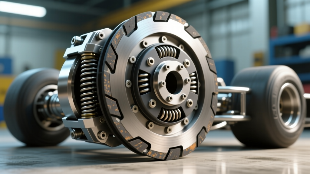
When a technician or driver encounters an AC clutch not engaging, the immediate assumption is often a simple low refrigerant charge. However, as drivetrain and auxiliary clutch specialists at AutoGearNexus, we approach the A/C compressor clutch as a precision electromagnetic friction device. Much like a transmission torque converter lock-up clutch or a heavy-duty PTO engagement mechanism, the A/C clutch relies on a strict balance of magnetic flux, mechanical tolerances, and thermodynamic interlocks. This technical deep-dive provides a comprehensive clutch system inspection checklist to isolate electrical, mechanical, and hydraulic failure modes in modern automotive A/C compressors.
Phase 1: Thermodynamic & Pressure Interlocks
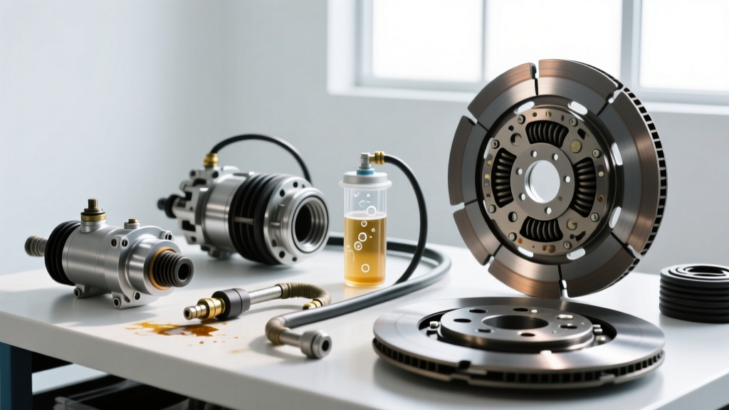
Before applying a single volt of electricity to the clutch coil, the system's thermodynamic state must be verified. The Powertrain Control Module (PCM) or dedicated HVAC control unit relies on a trinary or binary pressure transducer switch located on the high-side or low-side refrigerant line. If the system detects an anomaly, it will intentionally inhibit the clutch relay to prevent catastrophic compressor failure.
For legacy R134a systems, the low-pressure cutoff typically engages between 25 and 40 PSI, while the high-pressure cutoff triggers between 430 and 475 PSI. For the newer R1234yf refrigerant, these thresholds are slightly adjusted due to the different pressure-temperature curve of the HFO refrigerant. Connect a manifold gauge set to verify static and dynamic pressures. If the static pressure reads below 30 PSI on an 80°F day, you have a leak, and the PCM is correctly preventing engagement. Conversely, if the high side is spiked above 450 PSI with the engine off, you may have a restricted condenser, a blocked expansion valve, or an overcharged system. In modern CAN-bus equipped vehicles, a scan tool is mandatory to read the HVAC module's PID data for the pressure sensor voltage and the PCM's 'Clutch Relay Command' status.
Phase 2: Electrical & Electromagnetic Coil Verification
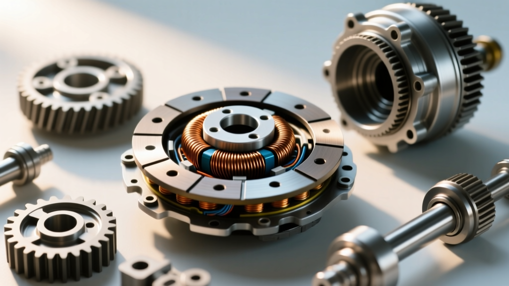
If the pressure parameters are within spec, the next phase of the clutch system inspection checklist targets the electromagnetic circuit. The A/C clutch coil is essentially a heavy-duty solenoid. When energized, it generates a magnetic field that pulls the steel friction hub against the spinning pulley assembly. To test the coil, disconnect the electrical pigtail and measure the resistance across the coil terminals using a digital multimeter.
A healthy 12-volt clutch coil typically exhibits a resistance between 3.0 and 4.5 Ohms at room temperature (20°C/68°F). If your multimeter reads 'OL' (Open Loop), the internal copper windings have fractured or the integrated thermal fuse has blown. Most clutch coils feature a non-resettable thermal protector embedded deep within the epoxy winding that severs the circuit at approximately 135°C (275°F) to prevent an electrical fire. If the resistance reads near zero, the coil has shorted internally.
| Compressor Manufacturer | Typical Coil Resistance (20°C) | Thermal Cutoff Threshold | Common Vehicle Applications |
|---|---|---|---|
| Denso (10S17C / 10PA17) | 3.2Ω - 3.8Ω | 135°C (275°F) | Toyota, Honda, GM |
| Sanden (SD7V16 / PXE16) | 3.5Ω - 4.2Ω | 140°C (284°F) | VW, Audi, Subaru |
| Delphi / Visteon (CVC) | 3.8Ω - 4.5Ω | 130°C (266°F) | Ford, Chrysler |
However, resistance testing alone is insufficient. You must perform a voltage drop test under load. Back-probe the clutch connector while the system is commanding engagement. You should read within 0.5 volts of the alternator's output (typically 13.5V to 14.2V). If you measure only 10.5V at the coil, the magnetic flux will be inadequate to pull the hub, resulting in a slipping clutch or complete failure to engage. This voltage drop is frequently caused by corroded pins in the underhood fuse block, failing PCM driver transistors, or degraded ground straps. For deeper engineering standards on mobile HVAC electrical systems, refer to the guidelines published by MACS (Mobile Air Climate Systems Association).
Phase 3: Mechanical Air Gap & Friction Surface Audit
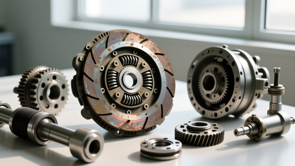
When the electrical circuit is verified and the coil receives full system voltage, yet the AC clutch is not engaging, the fault usually lies in the mechanical air gap. The magnetic pull of the coil decreases exponentially as the distance between the electromagnet and the armature (hub plate) increases, governed by the inverse-square law of magnetism. Over time, the friction surfaces of the pulley and the hub plate wear down, widening this critical air gap.
Consult the manufacturer's service manual, but generally, the acceptable air gap ranges from 0.4mm to 0.8mm (0.015 to 0.031 inches). Use a tapered feeler gauge to measure the gap at three equidistant points around the circumference of the clutch. If the gap exceeds 1.0mm, the magnetic field is simply too weak to overcome the tension of the hub return spring and the rotational inertia of the compressor shaft.
To correct this, you must shim the clutch hub. Remove the center retaining bolt (usually a 10mm or 12mm hex head, torqued to roughly 12-15 Nm). Use a specialized clutch puller or a two-jaw gear puller to extract the hub plate. Beneath the hub, you will find a series of thin steel spacer shims. Removing one or two shims (typically 0.1mm to 0.2mm thick) will reduce the air gap back into the optimal engagement window. Reinstall the hub, torque the center bolt to factory specifications, and re-verify the gap with your feeler gauge.
Phase 4: Drivetrain Accessory Load & Bearing Binding
Finally, we must consider the physical rotating assembly. The A/C compressor is driven by the serpentine accessory belt, meaning it is subject to the same drivetrain alignment and tensioning forces as the alternator and power steering pump. If the compressor's main shaft bearing is failing, or if the internal swash plate (in variable displacement units like the Sanden SD7V16) has suffered a mechanical seizure, the rotational resistance will exceed the clutch's holding torque capacity.
Symptoms of mechanical binding include a clutch that engages briefly, emits a harsh chirping or smoking odor, and then disengages. This rapid cycling occurs because the slipping friction surface generates immense heat, quickly triggering the coil's internal thermal cutoff switch. Once the coil cools, it re-engages, only to overheat again. To isolate this, remove the serpentine belt and spin the compressor clutch hub by hand. It should rotate smoothly with a consistent, mild viscous drag from the internal oil and refrigerant. Any grinding, notchiness, or hard spots indicate internal compressor failure or a seized shaft bearing, necessitating a complete compressor replacement rather than a simple clutch repair. Additional diagnostic parameters for compressor tolerances can be found in SAE International standards documentation for mobile refrigerant systems.
Component Replacement & Cost Analysis
When a failure is confirmed, understanding the replacement economics and part numbering is vital for both technicians and informed consumers. A complete A/C clutch assembly (comprising the pulley, bearing, electromagnetic coil, and friction hub) typically ranges from $80 to $180 for OEM-equivalent components from manufacturers like Four Seasons, GPD, or UAC. If the internal thermal fuse has blown but the friction surfaces are pristine, some specialists opt to replace only the coil, though this requires pressing the pulley bearing and coil out of the housing—a labor-intensive process that often justifies swapping the entire clutch assembly.
If the compressor shaft bearing or internal swash plate is seized, the entire compressor must be replaced. OEM compressors from Denso or Sanden generally cost between $350 and $700, while aftermarket remanufactured units range from $200 to $400. Remember that any compressor replacement mandates a system flush, a new accumulator/receiver-drier, and an expansion valve replacement to maintain warranty compliance. The labor and refrigerant recharge (especially for R1234yf, which costs significantly more per ounce than legacy R134a) can push the total repair invoice well past $1,200.
Diagnostic Summary Flowchart
To streamline your troubleshooting, follow this sequential diagnostic flowchart:
- Step 1: Verify System Pressures. Connect manifold gauges. Ensure static pressure is above 40 PSI and high-side is below 400 PSI.
- Step 2: Scan for Codes. Use an OBD-II scanner to check for HVAC/PCM codes related to the pressure transducer or clutch relay circuit.
- Step 3: Measure Coil Resistance. Disconnect the coil and verify 3.0 to 4.5 Ohms. Replace if OL or shorted.
- Step 4: Test Voltage Under Load. Back-probe the connector. Confirm >13.0V during PCM command. Repair wiring or relays if voltage drops.
- Step 5: Inspect Air Gap. Measure with a feeler gauge. Shim the hub if the gap exceeds 0.8mm.
- Step 6: Check Mechanical Binding. Remove the drive belt and rotate the hub by hand to rule out internal compressor seizure.