Introduction: Traditional Planetary vs. Continuously Variable Architectures
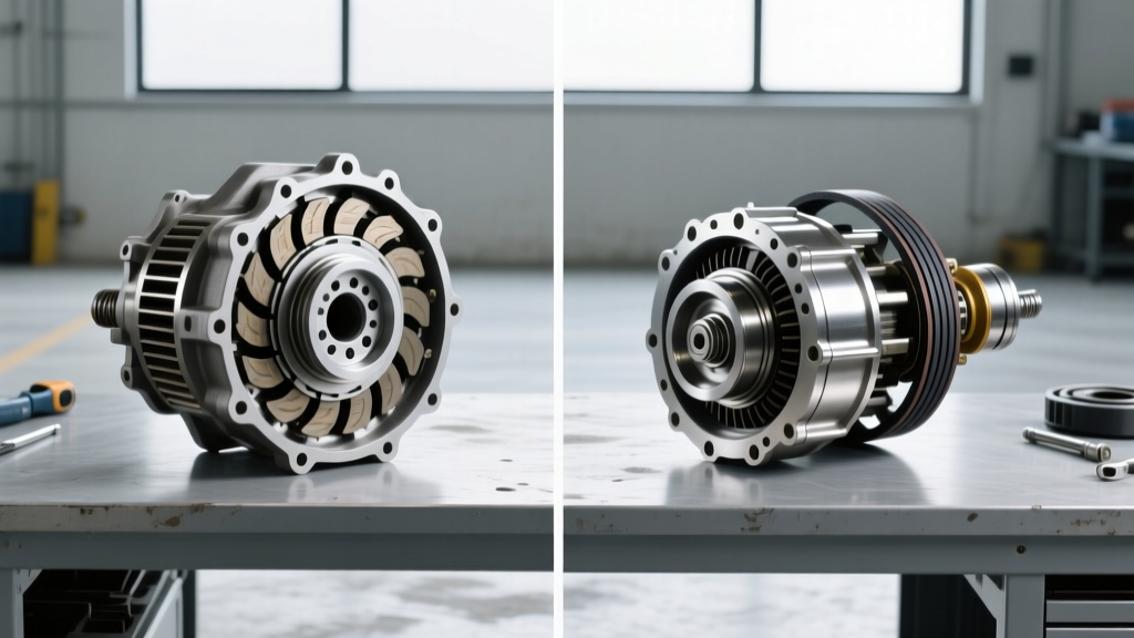
When diagnosing drivetrain shudder, slip, or lockup failures, automotive technicians frequently encounter two radically different transmission architectures: the traditional planetary automatic and the Continuously Variable Transmission (CVT). Ford's ubiquitous 6R80 transmission—a robust derivative of the ZF 6HP26—relies on a large-diameter fluid coupling torque converter to multiply engine torque and manage gear transitions. In stark contrast, modern CVTs (such as the Jatco JF016E/CVT8 found in Nissan, Chrysler, and Mitsubishi applications) utilize a much smaller torque converter strictly for initial vehicle launch and decoupling, relying on a push-belt or chain-and-pulley system for ratio changes.
As we navigate the 2026 diagnostic landscape, misdiagnosing torque converter clutch (TCC) shudder in a 6R80 as a CVT belt slip issue (or vice versa) can lead to catastrophic financial missteps. This step-by-step how-to guide will walk you through the precise diagnostic procedures, live data analysis, and mechanical verification steps required to accurately isolate torque converter faults across both platforms.
Core Hardware Differences: 6R80 vs. CVT Torque Converters
Before connecting a scan tool, it is critical to understand the mechanical divergences between these two systems. The 6R80 torque converter is designed to handle the massive low-end torque of Ford's 5.0L Coyote V8 and 3.5L EcoBoost engines, featuring a multi-plate lockup clutch for aggressive thermal management. CVT torque converters, however, are engineered for immediate lockup to maximize fuel economy, placing entirely different friction and thermal demands on the TCC lining.
| Specification | Ford 6R80 (ZF 6HP26 Base) | Jatco CVT8 (JF016E / JF017E) |
|---|---|---|
| Primary Function | Torque multiplication & gear shift cushioning | Launch decoupling & immediate lockup |
| TCC Lockup Strategy | Slipping/Modulated in 3rd-6th gears | Binary/Fast-ramp lockup at ~15 mph |
| Fluid Specification | MERCON LV (XT-10-QLVC) | Nissan NS-3 / OEM CVTF |
| Common Shudder RPM | 1,200 - 1,600 RPM (40-60 mph) | Idle to 2,000 RPM (Pulley/Belt induced) |
| Stall Speed Range | 2,000 - 2,400 RPM | N/A (Stall testing prohibited) |
Step 1: Fluid Condition and Specification Verification
The first step in any torque converter diagnosis is fluid analysis. The friction modifiers required for a 6R80 TCC are vastly different from those required for a CVT's wet start clutch and belt/pulley interface.
6R80 Fluid Inspection
Extract a sample using the dipstick tube or level check plug (located on the transmission pan). Ford's MERCON LV fluid is highly susceptible to thermal breakdown if the vehicle is used for heavy towing without an auxiliary cooler. If the fluid smells burnt or contains fine metallic particulate, the TCC friction material is likely delaminating. A service fill requires approximately 6.0 quarts, while a dry fill after a complete torque converter replacement requires 13.1 quarts. Always verify the fluid level at the precise transmission temperature specified on the dipstick (typically 180°F - 200°F).
CVT Fluid Inspection
CVTF (like Nissan NS-3) degrades differently. It loses its sheer stability, which directly impacts the hydraulic pressure required to clamp the CVT pulleys. If a CVT exhibits shudder, technicians often mistakenly blame the torque converter when the actual culprit is low line pressure causing the drive belt to slip on the pulleys. Always check the CVT fluid level using the manufacturer's specific temperature-to-height chart via the overflow plug.
Step 2: Live Data TCC Slip Analysis via OBD2
With the fluid verified, connect a bi-directional professional scan tool (e.g., Snap-on Zeus, Autel Ultra, or Ford IDS/FDRS). Monitoring the Torque Converter Clutch Slip PID is the most definitive way to separate a failing TCC from internal transmission wear.
Monitoring the 6R80 TCC Slip
- Commanded State: Drive the vehicle until it reaches 4th, 5th, or 6th gear. Ensure the TCC is commanded 'ON' or 'LOCKED' by the PCM.
- Slip RPM Calculation: Observe the
TCC_SLIP_RPMPID. A healthy 6R80 will show slip between 0 and 20 RPM when fully locked. If you observe slip fluctuating between 50 and 150 RPM under steady throttle, the TCC regulator valve bore in the valve body is likely worn—a common failure point documented by Sonnax. Alternatively, the TCC PWM solenoid may be failing. - Shudder Correlation: If the vehicle shudders at 50 mph and the TCC slip PID spikes erratically, you have confirmed a torque converter clutch or hydraulic apply circuit failure.
Monitoring CVT Lockup
In a CVT, the torque converter lockup clutch applies almost immediately after launch (often below 15 mph) to eliminate parasitic fluid coupling losses. If the scanner shows the TCC commanded 'LOCKED' but engine RPM flares without a corresponding increase in vehicle speed, the issue is rarely the CVT torque converter itself. Instead, this indicates a loss of hydraulic clamping pressure on the primary/secondary pulleys, or a failing stepper motor. According to the Automatic Transmission Rebuilders Association (ATRA), misdiagnosing CVT pulley slip as a torque converter failure is one of the most common errors in modern drivetrain repair.
Step 3: Safe Load Testing (Stall vs. Pressure)
Load testing is where the procedural divergence between the 6R80 and CVT becomes a matter of mechanical survival.
The 6R80 Stall Test Procedure
A traditional stall test is highly effective for the 6R80 to verify stator one-way clutch integrity and overall pump health.
- Ensure transmission fluid is at operating temperature (180°F+).
- Hold the brake pedal firmly to the floor.
- Apply wide-open throttle (WOT) for no more than 3 to 5 seconds.
- Record the maximum engine RPM. A healthy 6R80 should stall between 2,000 and 2,400 RPM.
The CVT Pressure Test Alternative
WARNING: Never perform a traditional brake-stall test on a CVT. Holding the brakes while applying throttle against a CVT torque converter will generate immense hydraulic heat and can instantly snap the push-belt or chain, destroying the variator pulleys. Instead, perform a hydraulic pressure test. Install a 500 PSI mechanical gauge into the forward clutch pressure port. At idle in Drive, pressure should typically read between 60-90 PSI. At stall (briefly, under 2 seconds), it should spike to line pressure (often 120-150+ PSI). If pressure drops when the TCC locks, the lockup control valve is bypassing fluid.
Step 4: Extraction, Hardware Inspection, and Torque Specs
If live data and load testing confirm a physical torque converter failure, extraction requires strict adherence to OEM torque specifications to prevent flexplate warping or pump gear destruction.
6R80 Removal and Installation Specs
- Bellhousing to Engine Block: The 6R80 uses E14 Torx bolts. Torque to 35 lb-ft (48 Nm).
- Flexplate to Crankshaft: Inspect for micro-cracks around the bolt holes (a known issue on high-torque EcoBoost applications). Torque to 65 lb-ft (88 Nm) in a star pattern.
- Torque Converter to Flexplate: The 6R80 uses 4 studs and nuts (typically M10x1.0). Torque to 22 lb-ft (30 Nm). Ensure the TC is fully seated into the transmission oil pump before tightening; the distance from the bellhousing mating surface to the TC stud pad should be approximately 11mm to 13mm. Failure to seat the TC will result in immediate pump gear destruction upon bellhousing bolt tightening.
CVT Removal Precautions
When removing a CVT torque converter, you must secure the input shaft and oil pump drive gear. Because CVTs lack traditional planetary gearsets to hold the input shaft stationary, the shaft can easily drop out of alignment during transmission lowering, damaging the delicate forward/reverse brake assemblies. Always use a dedicated CVT input shaft alignment tool during reinstallation.
2026 Replacement Costs and Sourcing
Understanding the financial landscape is crucial for advising customers. A remanufactured OEM-spec torque converter for a Ford 6R80 (covering F-150, Mustang, and Expedition applications) typically ranges from $350 to $550. Labor for a standard R&R (Remove and Replace) averages 6.5 to 8.0 hours, bringing the total shop ticket to roughly $1,100 - $1,600.
Conversely, while a CVT torque converter part itself may only cost $250 to $400, a failure that introduces metallic debris into the CVTF will almost always contaminate the valve body stepper motors and the delicate pulley surfaces. In 90% of CVT torque converter failure cases, a complete transmission teardown and variator inspection is mandatory, pushing the repair cost well past $3,500. Always install an inline magnetic fluid filter on the cooler return line post-repair to catch any remaining TCC particulate.
Summary
Diagnosing torque converter systems requires a fundamental understanding of the transmission architecture. The 6R80 relies on complex, modulated TCC slip managed by the valve body and PWM solenoids, making it prone to specific regulator valve wear and 40-50 Hz shudder. CVTs use the torque converter as a simple launch device, meaning shudder is more likely tied to pulley clamping pressure than the TCC itself. By following this step-by-step diagnostic protocol—verifying fluid, analyzing live TCC slip PIDs, executing safe load tests, and adhering to precise torque specs—technicians can confidently isolate and repair drivetrain faults without falling victim to costly misdiagnoses.