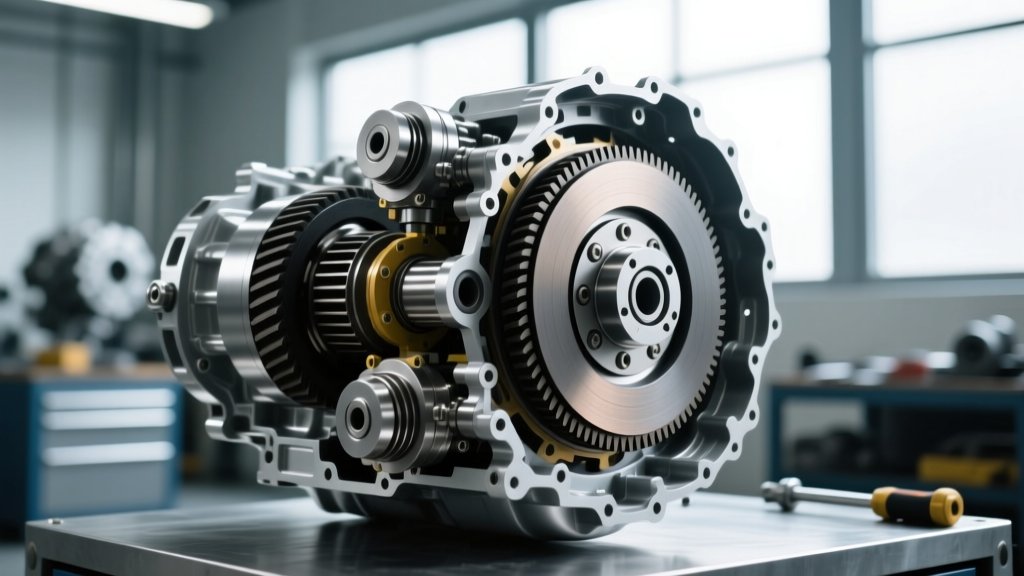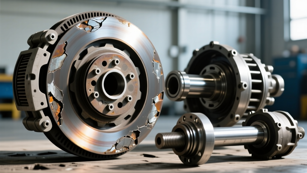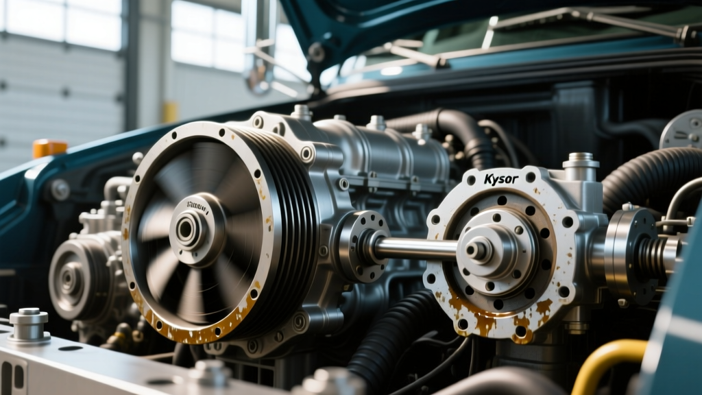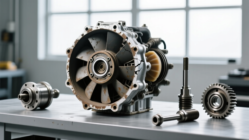
The Thermal Gatekeeper: Understanding the 6.0L Powerstroke Fan Clutch
In the ecosystem of the Ford 6.0L Powerstroke (2003-2007), thermal management is not just a luxury; it is the thin line between reliable towing and catastrophic engine failure. While transmission and drivetrain clutches manage torque transfer, the engine-driven fan clutch manages the immense heat rejected by the EGR system, the oil cooler, and the turbocharger. As we navigate the aftermarket and maintenance landscape in 2026, understanding the specific wear signs and lifespan indicators of this component is critical for any diesel technician or enthusiast.
The 6.0L Powerstroke primarily utilizes an Electro-Magnetic Controlled (EMC) fan clutch, though some early or specialized fleet models were equipped with heavy-duty viscous thermal clutches. Both designs are subject to severe degradation due to the engine's high-radiant heat environment. When the clutch fails to engage or disengage properly, it triggers a cascade of thermal and acoustic symptoms that must be diagnosed before proceeding with fan clutch removal 6.0 powerstroke procedures.
Lifespan Indicators: How Long Does a 6.0 Fan Clutch Last?
Unlike manual transmission friction clutches that wear based on driver engagement habits, the 6.0L fan clutch lifespan is dictated by thermal cycling, electrical load, and fluid shear (in viscous models).
- Viscous Models: Typically last between 80,000 and 110,000 miles. The silicone shear fluid inside the reservoir degrades over time, losing its viscosity and resulting in a perpetually slipping clutch.
- Electro-Magnetic (EMC) Models: Generally survive 100,000 to 150,000 miles. Failure is rarely mechanical; instead, the internal electromagnetic coil burns out due to heat soak from the radiator and intercooler, or the Hall-effect speed sensor fails.
A major lifespan accelerator on the 6.0L is a clogged oil cooler. When the oil cooler restricts coolant flow to the EGR cooler, the engine's overall thermal load spikes. The PCM responds by commanding the fan clutch to maximum duty cycle (85%+) almost continuously, accelerating coil burnout and bearing wear.
Critical Wear Signs of a Failing Fan Clutch
Diagnosing a failing fan clutch requires a multi-sensory approach, combining acoustic monitoring, thermal data logging via an OBD-II scanner, and physical resistance testing.
1. Acoustic Diagnostics: The 'Jet Engine' vs. The 'Click of Death'
A healthy viscous fan clutch will roar loudly for the first 30 to 60 seconds after a cold start as the silicone fluid redistributes, then quiet down as the bimetallic strip closes the valve. If your 6.0L sounds like a departing jet engine continuously while cruising at highway speeds, the clutch is mechanically locked. Conversely, if you hear a rhythmic metallic clicking or rattling from the fan hub at idle, the internal stator bearings or the electromagnetic armature air-gap has failed, requiring immediate replacement.
2. Thermal Inefficiency and Coolant Temp Delta
Using a bi-directional scan tool, monitor the Engine Coolant Temperature (ECT) and the Fan Speed Sensor RPM. If the PCM commands an 85% PWM (Pulse Width Modulated) duty cycle to the fan clutch, but the fan speed sensor reports less than 800 RPM at 2,500 engine RPM, the clutch is slipping. On a healthy 6.0L, an 85% command should yield fan speeds exceeding 2,200 RPM, pulling massive CFM through the radiator stack.
3. The Overheating Under Load Symptom
The most common wear sign reported by owners towing heavy trailers is a rapid spike in ECT when climbing grades. Because the slipping fan clutch cannot pull adequate air through the charge air cooler (CAC) and radiator, the intake air temperatures (IAT) rise, causing the PCM to pull timing and defuel the engine to protect the pistons.
Electrical Deep-Dive: Testing the EMC Coil and Sensor
Before initiating any mechanical disassembly, you must verify the electrical integrity of the EMC system. The PCM controls the fan clutch via a 12-volt PWM signal. The fan clutch assembly features a 3-pin connector: Power, Ground, and the Hall-effect sensor signal return.
- Disconnect the Pigtail: Locate the fan clutch connector near the top of the fan shroud. Disconnect it and inspect for pushed-back pins or corrosion, a common issue in 20-year-old harnesses.
- Measure Coil Resistance: Set your multimeter to Ohms. Probe the power and ground pins on the fan clutch side of the connector. At 68°F (20°C), the electromagnetic coil resistance should read between 2.2 and 4.5 Ohms. If the meter reads 'OL' (Open Loop), the internal coil is severed, and the clutch is dead.
- Verify Sensor Power: Probe the harness side of the connector with the key ON, engine OFF. You should see 12V reference on the power pin and a clean ground on the ground pin.
Expert Insight: Never attempt to jumper 12V directly to the EMC fan clutch pins to 'force' it on. The PCM uses a sophisticated PWM driver. Applying raw battery voltage can overheat the coil or damage the PCM's internal fan driver transistor, turning a $300 fan clutch job into a $1,200 PCM replacement.
Fan Clutch Diagnostic Trouble Codes (DTCs)
When the PCM detects a discrepancy between the commanded duty cycle and the actual fan speed reported by the Hall-effect sensor, it will set a DTC and often trigger a check engine light or a 'Wrench' icon.
| DTC | Description | Primary Failure Point |
|---|---|---|
| P0528 | Fan Speed Sensor Circuit No Signal | Open in sensor return wire or dead Hall-effect sensor |
| P0529 | Fan Speed Sensor Circuit Intermittent | Corroded connector, chafed harness near shroud |
| P0480 | Fan 1 Control Circuit Malfunction | Blown fuse, short to ground, or burnt EMC coil |
| P062B | Internal Control Module Fan Control Fault | PCM internal driver failure (rare, verify wiring first) |
Technical Guide: Fan Clutch Removal 6.0 Powerstroke
Once diagnostics confirm the clutch is faulty, physical removal requires specific tools and an understanding of Ford's fastener torque specifications. The 6.0L fan clutch is mounted directly to the water pump snout, meaning the entire assembly spins with the water pump pulley.
Required Tools and Parts
- 36mm Fan Clutch Wrench: (OTC 4585 or Ford 303-D015 equivalent). Do not use an adjustable wrench; the clearance is too tight and you will round the nut.
- Water Pump Pulley Holding Tool: Essential to prevent the serpentine belt from slipping and to lock the pulley while applying breakout torque.
- Replacement Part: Motorcraft YC3Z-8A616-BA (or current superseded severe-duty part number). Avoid cheap offshore knockoffs; their electromagnetic coils frequently fail within 10,000 miles. Expect to pay between $280 and $360 for an OEM unit in 2026.
Step-by-Step Removal Procedure
- Remove the Serpentine Belt: Use a 1/2-inch breaker bar on the automatic belt tensioner to relieve tension and slip the belt off the water pump pulley.
- Secure the Pulley: Install the pulley holding tool, bolting it to the water pump pulley's accessory holes. This locks the assembly in place.
- Break the Retaining Nut: Place the 36mm wrench on the fan clutch retaining nut. Crucial Note: The 6.0L Powerstroke water pump rotates clockwise (viewed from the front), which means the retaining nut is typically standard right-hand thread (turn counter-clockwise to loosen). However, due to years of heat cycling and torque, the breakout force can exceed 150 lb-ft. Use a dead-blow hammer to strike the end of the 36mm wrench handle sharply. Do not use a cheater pipe, as you risk snapping the water pump shaft.
- Unthread and Extract: Once broken loose, spin the 36mm nut off by hand. Carefully pull the fan clutch assembly straight forward, off the water pump snout. Be extremely careful not to let the heavy clutch drop onto the radiator fins or intercooler.
- Inspect the Water Pump Snout: Before installing the new unit, clean the mating surface of the water pump snout with a wire brush and brake cleaner. Check the water pump weep hole for signs of coolant leakage; if the water pump is failing, replace it simultaneously to save labor.
Installation and Torque Specifications
Thread the new Motorcraft fan clutch onto the water pump snout by hand to prevent cross-threading. Tighten the 36mm retaining nut to the factory specification of 45 Nm (33 lb-ft). Reinstall the serpentine belt, reconnect the electrical pigtail (ensuring the weather-pack seal clicks into place), and clear any stored DTCs using your scan tool.
Final Thoughts on 6.0L Thermal Management
Replacing the fan clutch is only half the battle if the underlying thermal restrictions are not addressed. As documented extensively by the Ford-Trucks technical community, a failing fan clutch is often the victim, not the culprit, of the 6.0L's inherent cooling system flaws. Always verify that your engine oil cooler delta temperatures (ECT vs. EOT) are within 15°F under load. If the oil cooler is clogged, your brand-new fan clutch will be forced to operate at maximum duty cycle, drastically shortening its lifespan. For verified OEM part cross-references and updated technical service bulletins, always consult the official Motorcraft parts catalog before ordering components. By combining rigorous electrical diagnostics with precise mechanical installation, you can restore your 6.0L Powerstroke's cooling capacity and ensure reliable performance for the next 100,000 miles.