Decoding the Automobile Drivetrain Diagram: AWD vs. 4WD
When it comes to preventive maintenance, treating an All-Wheel Drive (AWD) system the same as a traditional Four-Wheel Drive (4WD) system is a costly mistake. While both configurations send power to all four wheels, their internal architectures, torque distribution methods, and fluid requirements are vastly different. As of 2026, with the proliferation of complex electro-hydraulic clutch packs and active torque-vectoring differentials, understanding your specific layout is no longer optional—it is critical for drivetrain longevity.
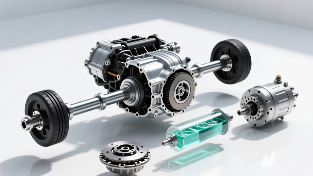
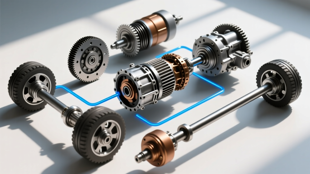
The most effective way to grasp these differences and plan your maintenance schedule is by studying an automobile drivetrain diagram. This schematic acts as your roadmap, illustrating power flow from the transmission output shaft, through the transfer case or center coupling, and out to the axles. In this guide, we will break down the mechanical differences between AWD and 4WD, provide exact maintenance specifications, and show you how to leverage drivetrain diagrams for proactive servicing.
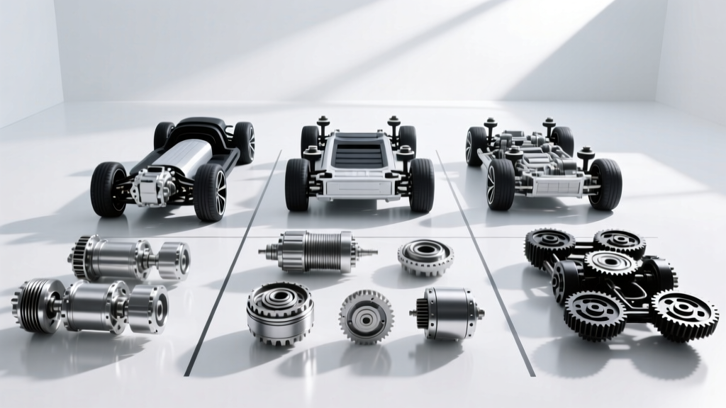
The Core Architectural Differences
Before draining a single drop of fluid, you must identify whether your vehicle utilizes a dedicated transfer case with a locking mechanism (4WD) or a center differential/clutch-pack coupling (AWD). According to engineering data from BorgWarner, modern torque-transfer devices rely on highly specific friction modifiers that are entirely incompatible across different system types.
| Feature | Traditional 4WD (Part-Time/Full-Time) | Modern AWD (On-Demand/Full-Time) |
|---|---|---|
| Power Transfer Device | Gear-driven or chain-driven Transfer Case (e.g., NV241, BW 4406) | Clutch-Pack Coupling (e.g., Haldex) or Center Differential |
| Front Axle Engagement | Manual/Auto locking hubs or vacuum-actuated axle disconnect | Always engaged; torque varies via clutch slip |
| Primary Fluid Type | ATF+4, Dexron VI, or specific Synchromesh (e.g., AutoTrak II) | Specialized Friction-Modified Gear Oil (e.g., VAG G 060 175 A2) |
| Service Interval | 30,000 - 60,000 miles (depending on use) | 20,000 - 40,000 miles (clutch packs degrade faster) |
| Pavement Bind-Up | High risk in 4-High/4-Low (no center diff) | None (center diff or clutch slip accommodates wheel speed variance) |
Preventive Maintenance: AWD Systems (Clutch-Packs & Center Diffs)
Most modern transverse-engine AWD vehicles (such as those from Volkswagen, Audi, Volvo, and Ford) utilize a rear power take-off (PTO) and an electronically controlled multi-plate clutch coupling, commonly known as a Haldex unit. When reviewing an automobile drivetrain diagram for these vehicles, you will notice the absence of a traditional heavy-duty transfer case. Instead, power is sent rearward via a two-piece driveshaft to the coupling, which sits directly in front of the rear differential.
Haldex Gen 4 and Gen 5 Servicing
The Haldex coupling relies on a specialized electro-hydraulic pump to compress clutch plates. The fluid in this system does not just lubricate; it acts as a hydraulic medium. Over time, the friction material from the clutch plates contaminates the fluid, turning it into an abrasive sludge that destroys the pump strainer.
- Fluid Specification: Use only OEM-approved fluid (e.g., VAG Part No. G 060 175 A2). Aftermarket alternatives often lack the precise friction modifiers required for the ECU's torque-request algorithms.
- Capacity: Typically 650ml to 850ml, depending on the exact generation and housing.
- The Gen 5 Strainer Trap: Unlike Gen 4, the Gen 5 Haldex does not have an easily accessible inline filter. Instead, it uses a suction strainer directly on the pump motor. During a fluid change, you must drop the pump motor (secured by three T30 Torx bolts) and clean the metal mesh screen with brake cleaner. Skipping this step is the #1 cause of premature AWD pump failure.
- Torque Specs: Drain plug: 15 Nm (11 lb-ft). Fill plug: 30 Nm (22 lb-ft). Pump motor bolts: 10 Nm (7 lb-ft).
Preventive Maintenance: Traditional 4WD Systems
Trucks and dedicated off-road SUVs (like the Jeep Wrangler, Toyota 4Runner, and Ford Super Duty) utilize traditional transfer cases. Consulting the automobile drivetrain diagram for a body-on-frame truck reveals a heavy-duty chain or gear set that physically locks the front and rear output shafts together in 4WD mode.
Transfer Case and Vent Tube Maintenance
Let's look at the ubiquitous New Venture NV241 (used in Jeep Wrangler JKs) and the BorgWarner 4406 (found in Ford Super Duties). These units endure massive shock loads and require meticulous fluid maintenance.
- NV241 (Jeep/Dodge): Requires Mopar ATF+4. Do not use standard gear oil; the synchronizers and chain require the specific friction profile of ATF+4. Capacity is roughly 2.5 pints. Drain and fill plug torque: 15-20 lb-ft.
- BW 4406 (Ford): Depending on the year, this requires Motorcraft XL-12 Transfer Case Fluid or Mercon ATF. Capacity is approximately 2.0 quarts. Fill plug torque: 20-27 Nm (15-20 lb-ft).
- GM AutoTrac (NV246/NV263): These active transfer cases require AutoTrak II fluid. Using standard ATF will cause severe clutch chatter and eventual failure of the internal encoder motor.
Critical Expert Tip: Always trace the transfer case vent tube during your 4WD maintenance routine. The diagram will show a small hose routing from the top of the transfer case up into the engine bay or frame rail. If this tube becomes clogged with mud or debris, the internal pressure from heat expansion will blow out the rear output shaft seal, leading to catastrophic fluid loss and transfer case seizure.
Using Your Drivetrain Diagram for Troubleshooting
An automobile drivetrain diagram is not just for assembly; it is a diagnostic tool. When you experience driveline vibration, clunking, or binding, the diagram helps you isolate the fault by understanding the power path and component phasing.
- U-Joint Phasing and CV Angles: The diagram illustrates the relationship between the transmission output, the transfer case, and the axle pinions. If you have lifted your vehicle, the diagram helps you visualize the operating angles of the CV joints and U-joints. Operating a standard U-joint beyond 3 degrees of variance between the transmission and pinion yoke will cause harmonic vibrations that destroy the transfer case output bearing.
- Driveline Bind-Up Diagnosis: If your 4WD vehicle 'hops' or binds during tight turns on dry pavement, the diagram confirms whether you are in a locked part-time 4WD mode (no center differential) or if your full-time 4WD center differential is failing to unlock due to a seized viscous coupler or faulty actuator motor.
- Locating Hidden Fill Plugs: On modern unibody SUVs, the rear differential and PTO fill plugs are often obscured by exhaust heat shields or aerodynamic crossmembers. The factory diagram provides the exact X/Y coordinates relative to the axle centerline, saving hours of blind probing.
2026 Maintenance Cost Breakdown & Intervals
Proactive maintenance is significantly cheaper than replacing a burned-out Haldex coupling or a seized transfer case chain. Below is a realistic pricing guide for independent shop rates and DIY costs in 2026.
| Service Item | Interval | DIY Fluid Cost | Shop Labor Estimate |
|---|---|---|---|
| AWD Haldex Coupling (Fluid & Strainer) | 20,000 - 30,000 miles | $45 - $75 | $200 - $350 |
| 4WD Transfer Case (ATF+4 / AutoTrak II) | 30,000 - 50,000 miles | $25 - $50 | $120 - $180 |
| Front/Rear Differential (75W-90 Synthetic) | 30,000 - 60,000 miles | $30 - $60 per axle | $100 - $150 per axle |
| Transfer Case Fluid + Vent Tube Inspection | Every oil change (visual) | $0 | Included in inspection |
Final Thoughts on Drivetrain Longevity
Whether you are crawling over rocks in a part-time 4WD rig or commuting through snow in an on-demand AWD crossover, the fluids inside your torque-transfer devices are the only barrier against metal-on-metal destruction. By taking the time to study your specific automobile drivetrain diagram, you can identify the exact fluid specifications, locate hidden service ports, and understand the mechanical limits of your system. For further engineering insights into torque vectoring and transfer case design, refer to the technical publications available through SAE International and the drivetrain manufacturing archives at Tremec. Stay proactive, follow the torque specs, and your drivetrain will easily outlast the vehicle's powertrain warranty.