Mastering the 6R80: Electrical Troubleshooting and Range Sensor Dynamics
The 2011 Ford F-150 marked a pivotal era for the Blue Oval, introducing the robust 6R80 six-speed automatic transmission. Based on the legendary ZF 6HP26 architecture, the 6R80 is a marvel of hydraulic and electronic integration. However, as these trucks age, the external electrical components—specifically the Transmission Range (TR) sensor—become prime candidates for degradation. For fleet managers, master technicians, and advanced DIYers, understanding the nuances of a 2011 Ford F150 transmission range sensor replacement is not just about swapping a part; it is about executing a comprehensive electrical troubleshooting protocol to ensure long-term drivability.
From a preventive maintenance perspective, ignoring minor PRNDL display glitches or intermittent no-start conditions can lead to catastrophic TCM (Transmission Control Module) confusion, resulting in limp-mode defaults or unexpected neutral drops at highway speeds. This guide dives deep into the electrical diagnostics, precise mechanical alignment, and preventive wiring care required to maintain the 6R80's electronic integrity in 2026 and beyond.
The Anatomy of a 6R80 Range Sensor Failure
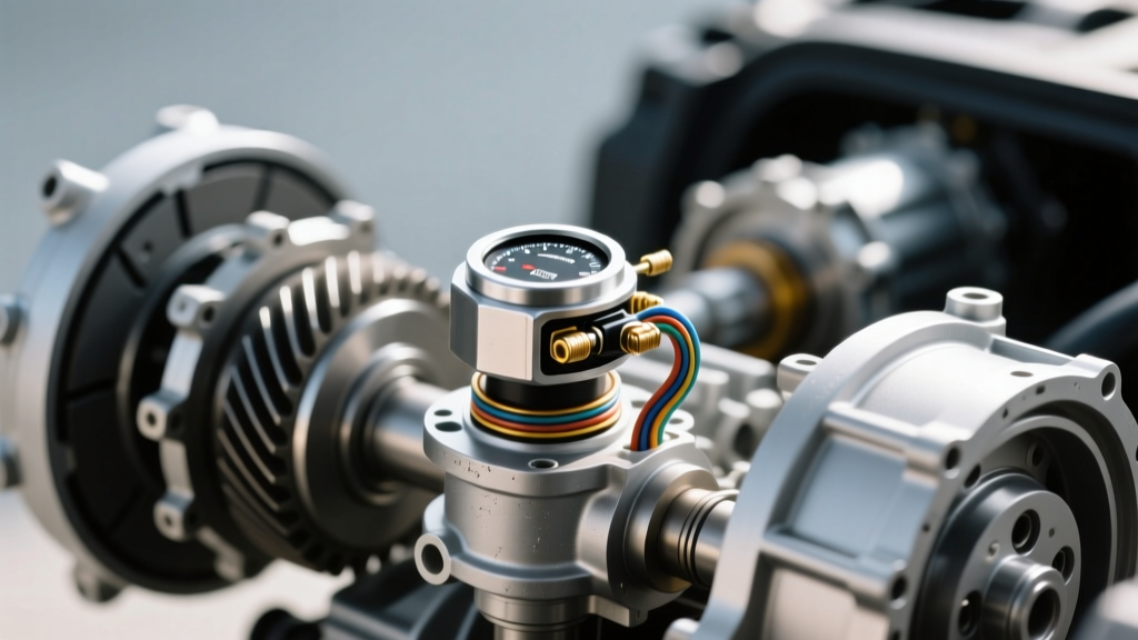
The TR sensor, often referred to as the neutral safety switch or PRNDL switch, is mounted externally on the driver's side of the 6R80 transmission case. It translates the physical position of the manual valve lever into a digital or analog resistance signal that the PCM/TCM uses for three critical functions:
- Starter Interlock Logic: Preventing the engine from cranking unless the selector is in Park or Neutral.
- Shift Scheduling: Informing the TCM of the driver's intended gear range to adjust line pressure and shift maps.
- Reverse Lamp Actuation: Completing the circuit for the backup lights when the manual shaft rotates to the 'R' detent.
Failure rarely stems from the internal wiper contacts alone. In the 2011 F-150, the primary culprit is galvanic corrosion at the 12-pin harness connector, exacerbated by road salt, thermal cycling, and vibration-induced fretting. When moisture breaches the weather-pack seals, copper oxidation creates high-resistance voltage drops that mimic internal sensor failures, throwing phantom P0705-P0708 diagnostic trouble codes.
Preventive Electrical Troubleshooting: Beyond the Scan Tool
Before committing to a full 2011 Ford F150 transmission range sensor replacement, a rigorous electrical diagnostic sequence must be performed. Replacing a perfectly good sensor due to a chafed wire or corroded pin is a common pitfall. According to diagnostic standards outlined by SAE International, verifying circuit integrity is mandatory before condemning any solid-state or resistive sensor.
Step 1: Analyzing the DTC Matrix
When the TCM detects an anomaly in the TR circuit, it logs specific OBD-II codes. Understanding their electrical implications is vital:
- P0705 (Transmission Range Sensor Circuit Malfunction): The PCM receives a signal that does not match any valid gear combination (e.g., Park and Drive signals active simultaneously). This usually indicates a short between adjacent pins in the connector.
- P0706 (Transmission Range Sensor Circuit Range/Performance): The sensor signal is erratic or jumps between gears without the physical lever moving. Often caused by worn internal wiper tracks or a loose manual shaft nut.
- P0707 (Transmission Range Sensor Circuit Low Input): The signal circuit is shorted to ground, or the 5V reference wire is severed.
- P0708 (Transmission Range Sensor Circuit High Input): An open circuit condition. The signal wire is broken, or the sensor ground path has failed due to corrosion.
Step 2: Pin-Out Continuity and Voltage Drop Testing
Using a high-impedance Digital Multimeter (DMM), back-probe the TR sensor connector with the ignition in the 'ON' position (engine off). Do not pierce the wire insulation, as this invites future corrosion. Below is the expected reference data for the 6R80 external TR sensor.
| Gear Position | Signal Circuit State | Expected Voltage (5V Ref) | Common Failure Mode |
|---|---|---|---|
| Park (P) | Circuit Closed to Ground | ~0.15V - 0.40V | High resistance (Corroded Pin 3) |
| Reverse (R) | Circuit Closed to Ground | ~0.15V - 0.40V | Backup lamps shorted to 12V |
| Neutral (N) | Circuit Closed to Ground | ~0.15V - 0.40V | No-start condition (Open Circuit) |
| Drive (D) | Circuit Closed to Ground | ~0.15V - 0.40V | Fretting on Pin 7 (Signal Drop) |
| Overdrive (OD) | Circuit Closed to Ground | ~0.15V - 0.40V | Internal wiper track wear |
If the voltage reads 4.8V to 5.0V across all positions, you have an open ground circuit. Trace the ground wire back to the chassis grounding point (typically located near the left frame rail) and inspect for rust. If the voltage fluctuates wildly while wiggling the harness, the fault lies in the wiring loom, not the sensor itself.
Execution: 2011 Ford F150 Transmission Range Sensor Replacement
Once electrical troubleshooting confirms the sensor is internally faulted, proceed with the mechanical replacement. As of 2026, the OEM Motorcraft part number SW-7106 (or engineering number 9L3Z-7F293-A) remains the gold standard. While aftermarket alternatives exist, Ford Motor Company Support documentation and field data heavily favor OEM components for the 6R80 due to the precise resistance tolerances required by the ZF-derived TCM logic.
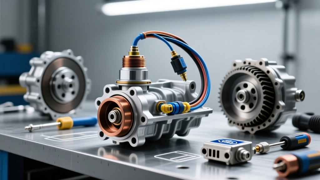
Required Tools and Safety Prep
- Motorcraft SW-7106 TR Sensor
- 8mm and 15mm sockets with torque wrench
- TR Sensor Alignment Tool (or careful use of factory alignment marks)
- Electrical contact cleaner and dielectric grease
- Safety glasses and wheel chocks
Safety Warning: Chock the rear wheels securely. Disconnect the negative battery terminal to prevent accidental shorting of the starter solenoid circuit while working near the manual lever.
Step-by-Step Removal and Installation
- Access the Manual Lever: Locate the shift linkage cable on the driver's side of the 6R80 case. Remove the retaining clip and slide the cable off the manual lever ball stud.
- Remove the Manual Lever Nut: Use a 15mm socket to remove the nut securing the manual lever to the transmission shaft. Carefully pull the lever off the splined shaft. Note the position of the flat spot on the shaft.
- Unbolt the TR Sensor: Disconnect the 12-pin electrical connector by pressing the locking tab. Remove the two 8mm mounting bolts securing the sensor to the case. Gently slide the sensor off the manual shaft.
- Prepare the New Sensor: Before installation, apply a thin layer of dielectric grease to the new sensor's harness connector pins to prevent future moisture ingress. Do not rotate the inner hub of the new sensor yet.
- Align and Install: The most critical step in any 2011 Ford F150 transmission range sensor replacement is alignment. The inner hub of the sensor must match the physical detent of the transmission's manual valve. Align the notch on the sensor's inner sleeve with the flat spot on the manual shaft. Slide the sensor onto the case.
- Torque Specifications: Install the two 8mm mounting bolts and torque them to 89 lb-in (10 Nm). Over-torquing can crack the plastic sensor housing, leading to immediate water intrusion.
- Reattach Manual Lever: Place the manual lever back onto the shaft, aligning it with the sensor's external pin. Torque the 15mm retaining nut to 37 lb-ft (50 Nm).
- Reconnect Linkage and Battery: Reattach the shift cable, reconnect the 12-pin electrical connector until it clicks, and restore battery power.
Post-Replacement Calibration and Preventive Maintenance
Unlike modern mechatronic units that require proprietary bidirectional scan tool recalibrations, the external TR sensor on the 6R80 is largely a 'plug-and-play' mechanical alignment. However, you must verify the alignment electronically. Turn the ignition to 'ON' and have an assistant slowly move the shifter through all detents while you monitor the PRNDL display on the instrument cluster and the backup lamps. If the display is off by half a gear, loosen the 8mm mounting bolts and slightly rotate the sensor housing until the digital readout perfectly matches the physical shifter position.
Long-Term Wiring Harness Preventive Care
To ensure the longevity of your repair and adhere to a strict preventive maintenance schedule, address the wiring environment. The 6R80 harness is routed dangerously close to the exhaust crossover and the bellhousing, making it susceptible to thermal degradation and chafing.
- Loom Wrapping: Inspect the final 18 inches of the harness leading to the TR sensor. If the factory split-loom is cracked, replace it with high-temperature Tesa tape or fiberglass sleeving rated for 300°F.
- Connector Sealing: Always use a marine-grade dielectric grease (such as Nyogel 760G) on the connector seal. Standard silicone grease can sometimes swell certain rubber weather-pack materials over time.
- Ziptie Routing: Ensure the harness is secured away from the manual lever's rotational path. A zip-tie failure here can result in the lever severing the TR sensor wires, causing an immediate P0708 code and a no-start condition.
Conclusion
Treating a 2011 Ford F150 transmission range sensor replacement as a simple bolt-on repair is a disservice to the complex electronic ecosystem of the 6R80 transmission. By integrating thorough electrical troubleshooting, precise torque and alignment specifications, and proactive wiring maintenance, you safeguard the vehicle against unpredictable shift behaviors and starter interlock failures. Regular inspection of the 12-pin connector during routine transmission fluid services remains the most cost-effective preventive measure for F-150 owners navigating the demands of modern towing and daily driving. For further technical service bulletins regarding the 6R80 platform, fleet managers should routinely consult the National Highway Traffic Safety Administration (NHTSA) database to stay ahead of manufacturer-identified electrical anomalies.