The Role of Speed Sensors in High-Performance TCM Logic
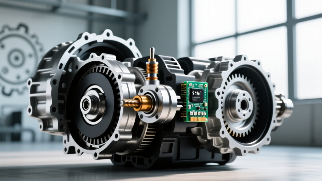
Modern automatic transmissions—such as the GM 10L90, Ford 10R80, and ZF 8HP series—are essentially computer-controlled hydraulic systems. The Transmission Control Module (TCM) relies on a closed-loop electronic control system to calculate shift timing, line pressure, and torque converter clutch (TCC) lockup. At the very foundation of this electronic ecosystem are the Input Speed Sensor (ISS) and Output Speed Sensor (OSS). For performance applications pushing beyond 700 horsepower, factory sensor resolution and thermal tolerances often become the weak link in the drivetrain.
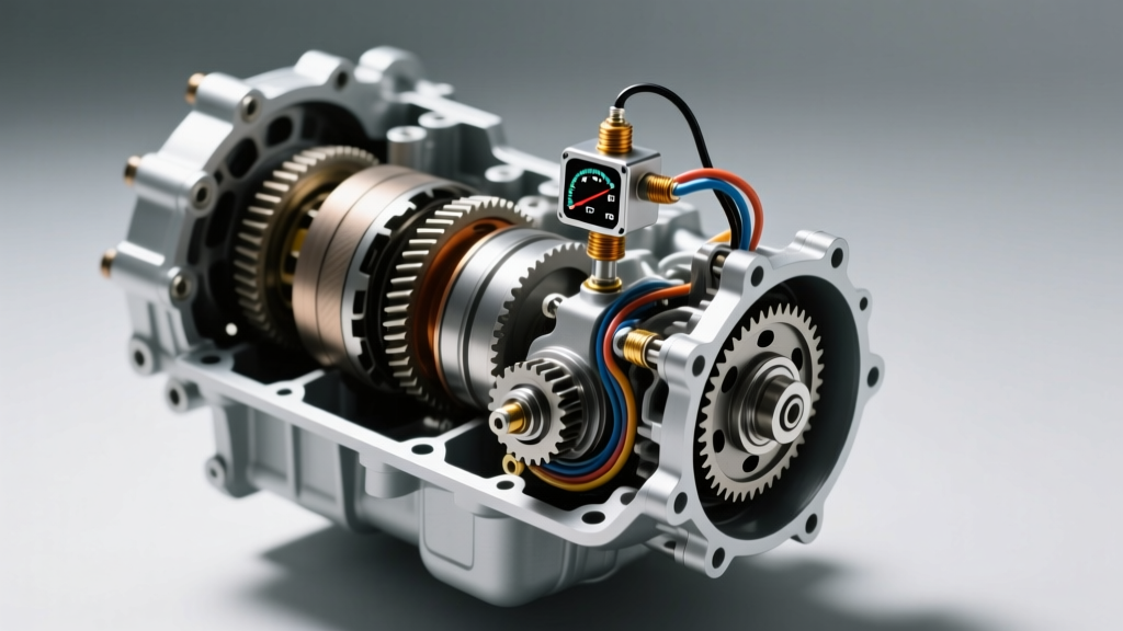
The TCM determines clutch slip by comparing the ISS reading against the OSS reading multiplied by the current gear ratio. If the calculated slip deviates from the TCM's programmed threshold for more than a few milliseconds, the system triggers fail-safes. In a high-horsepower track environment, aggressive launches and rapid RPM spikes can cause factory magnetic pickups to misread stator teeth, resulting in phantom slip DTCs like P0717 (Input Speed Sensor No Signal) or P0722. Understanding the nuances of performance transmission sensor replacement is critical for maintaining electronic control system integrity under extreme loads.
Why OEM Sensors Limit High-Horsepower Builds
Original Equipment Manufacturer (OEM) speed sensors are typically Hall-effect or magneto-resistive devices designed for cost-efficiency and standard thermal operating ranges (up to 265°F / 129°C). However, in modified vehicles utilizing high-stall torque converters and aggressive line pressure tuning, internal transmission fluid temperatures can easily spike past 280°F during track use.
- Thermal Drift: As internal temperatures exceed OEM design limits, the sensor's internal circuitry experiences resistance drift, altering the square-wave signal voltage sent to the TCM.
- EMI Interference: High-horsepower builds often utilize aftermarket ignition systems and high-amperage alternators. Poorly shielded OEM sensor wiring is highly susceptible to Electromagnetic Interference (EMI), causing signal dropouts.
- Stator Harmonics: At extreme RPMs (e.g., 8,500+ RPM engine speed through a 1:1 ratio), the physical vibration of the transmission shaft can cause the OEM sensor air gap to fluctuate, leading to erratic TCM slip calculations.
Performance Transmission Sensor Replacement: Upgrading the Hardware
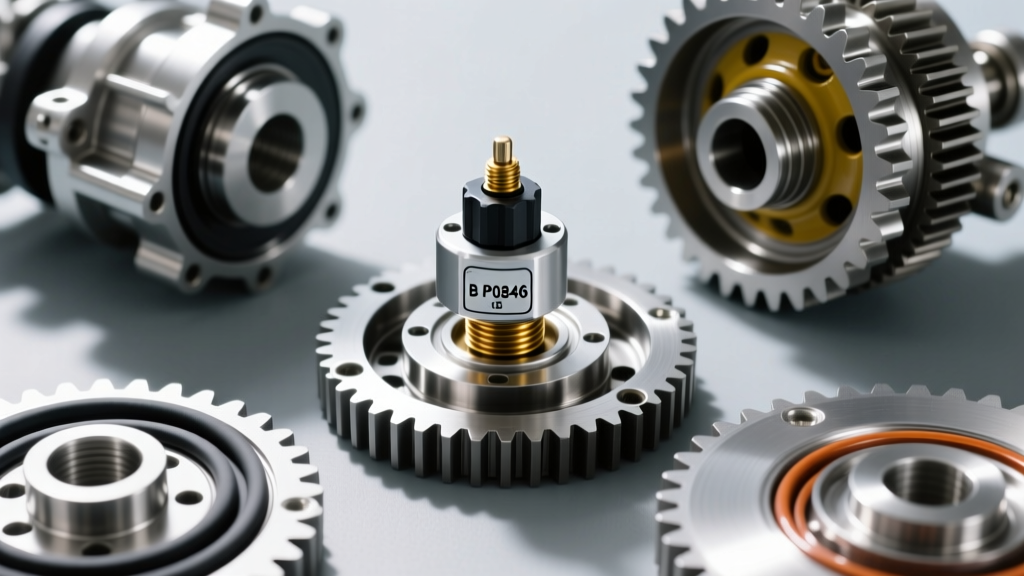
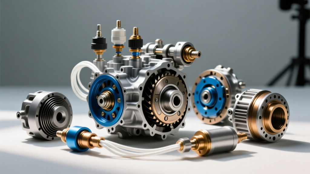
When executing a performance transmission sensor replacement, the goal is not merely to swap a broken part, but to upgrade the signal fidelity and thermal resilience of the electronic control system. High-end performance builds require sensors with matched, high-temperature EPDM seals, gold-plated connector pins to resist galvanic corrosion, and Teflon-jacketed internal wiring.
| Specification | Standard OEM Sensor | Performance / Upgraded Sensor |
|---|---|---|
| Operating Temp Limit | 265°F (129°C) | 315°F (157°C)+ |
| Signal Type | Standard Hall-Effect | Shielded Magneto-Resistive |
| Air Gap Tolerance | 0.5mm - 1.2mm | 0.3mm - 0.8mm (Tighter) |
| Wiring Jacket | PVC / Cross-linked PE | PTFE (Teflon) / Fiberglass |
| Connector Pins | Tin-Plated | Gold-Plated |
Platform-Specific Upgrade Guides
GM 8L90 and 10L90 Architecture
The GM 10-speed (10L90) utilizes a highly complex internal wiring harness and a dual-function ISS/OSS setup mounted directly to the valve body stator support. When performing a transmission sensor replacement on these units for 800+ HP applications, it is highly recommended to replace the entire internal wiring harness (molded leadframe) alongside the sensors. The plastic looms on early 2018-2020 models are known to warp under high heat, altering the sensor air gap.
Part Reference: ACDelco 24285748 (ISS) and 24288982 (OSS). For extreme builds, aftermarket performance wiring harnesses featuring integrated EMI shielding are available from specialized drivetrain manufacturers. Always verify the stator teeth for metallic debris before installing the new sensor, as a single metal shaving on the magnetic pickup will ruin the signal waveform.
Ford 10R80 and ZF 8HP Considerations
The Ford 10R80 shares much of its architecture with the ZF 8HP, but utilizes a unique Mechatronic unit (valve body and TCM combined). The speed sensors on the 10R80 are integrated into the C-axis and D-axis stators. A common failure point in high-HP Mustangs and F-150s is not the sensor itself, but the micro-connector on the Mechatronic sleeve. When replacing the OSS (Part # JL3Z-7M101-A), inspect the sleeve connector for pushed-back pins. Upgrading to a reinforced Sonnax-style sleeve or utilizing a high-temp ceramic connector housing ensures the TCM maintains uninterrupted communication with the speed sensors.
TCM Calibration: Tuning the Slip Algorithms
Hardware replacement is only half the battle. The electronic control system must be recalibrated to understand the new sensor's signal characteristics and the physical reality of a high-horsepower drivetrain. Using software like the HP Tuners VCM Suite, calibrators must adjust the TCM's slip threshold tables.
Tuning Insight: When upgrading to high-friction clutch packs and heavier return springs, the physical clutch engagement time decreases. If the TCM slip tables are not widened to accommodate the new hardware and the upgraded sensor's faster response time, the TCM will falsely detect 'shift flare' or 'slip' and aggressively over-pressurize the shift, resulting in harsh, binding shifts.
Key TCM parameters to modify post-sensor replacement include:
- Max Allowable Slip (RPM): Increase by 15-20% during WOT (Wide Open Throttle) shift phases to prevent phantom limp-mode triggers.
- Slip Fault Timer (Seconds): Extend the diagnostic timer from the OEM 0.5 seconds to 1.2 seconds to allow for drivetrain shock during hard launches.
- Sensor Signal Dropout Threshold: Adjust the minimum voltage parameter to filter out EMI noise generated by aftermarket ignition coils.
Installation Precision and Torque Specifications
The electronic control system's accuracy is entirely dependent on the physical installation of the speed sensors. An improper air gap will result in a weak square-wave signal, causing the TCM to miscalculate vehicle speed and shift pressure.
- O-Ring Lubrication: NEVER use petroleum jelly or silicone grease on sensor O-rings. These substances will cause the EPDM rubber to swell and extrude into the valve body passages. Use only the assembly's specific ATF (e.g., Motorcraft MERCON ULV or Dexron ULV) to lubricate the O-rings during installation.
- Fastener Torque: Most GM and Ford M6x1.0 sensor retaining bolts must be torqued to exactly 10 Nm (89 lb-in). Over-torquing can crack the sensor's thermoplastic housing, leading to fluid ingress and immediate electrical failure.
- Air Gap Verification: Use a non-magnetic feeler gauge to verify the gap between the sensor tip and the stator reluctor wheel. Target specification is typically 0.5mm to 0.8mm. If the stator is worn, replace it; do not attempt to shim the sensor.
Cost vs. Performance ROI Analysis
Investing in high-quality components during a transmission sensor replacement yields massive dividends in drivetrain reliability. Below is a realistic cost breakdown for a comprehensive performance sensor and electronic control upgrade.
| Component / Service | Estimated Cost (USD) | Performance Benefit |
|---|---|---|
| OEM ISS/OSS Sensor Pair | $80 - $140 | Restores baseline reliability |
| High-Temp Internal Wiring Harness | $150 - $280 | Eliminates EMI and thermal shorts |
| Upgraded Stator / Reluctor Ring | $90 - $160 | Ensures perfect air gap and signal |
| TCM Custom Calibration (Tuning) | $450 - $800 | Optimizes slip logic for new hardware |
By addressing the entire electronic control ecosystem rather than simply swapping a failed sensor, builders ensure that the TCM has the precise, high-fidelity data required to command 1,500+ PSI line pressures safely. In the realm of modern performance automatics, the speed sensor is the eyes of the TCM; if the TCM cannot see the drivetrain accurately, no amount of mechanical reinforcement will save the transmission from catastrophic self-destruction.