The Architecture of Transmission Electronic Control Systems
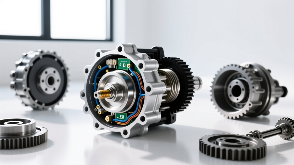
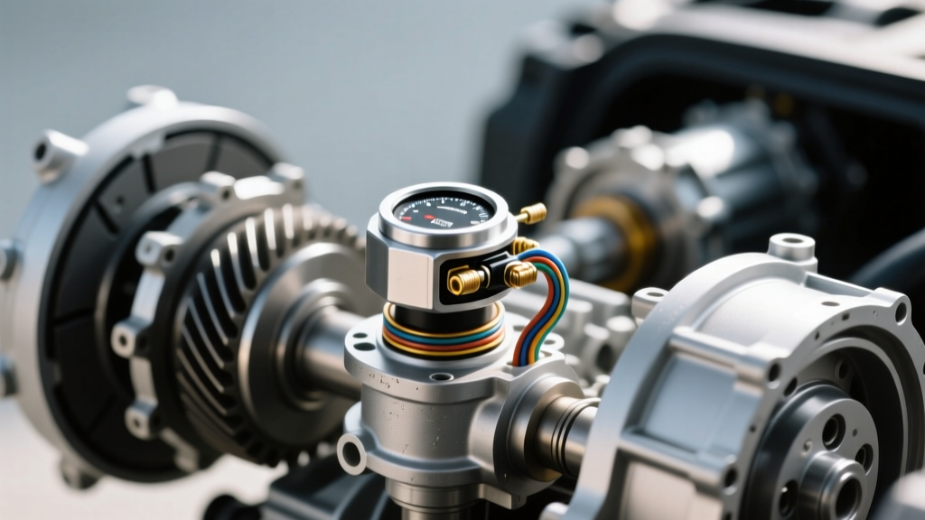
Modern automatic transmissions are marvels of electro-hydraulic engineering, relying on a complex network of solenoids, pressure transducers, and speed sensors to execute shifts in milliseconds. At the very foundation of this electronic control system is the Transmission Range (TR) sensor. Often overlooked by novice tuners, the TR sensor (or Internal Mode Switch) is the primary communicator between the driver's gear selector and the Transmission Control Module (TCM). When building a high-horsepower platform or upgrading to a manual valve body, addressing a faulty transmission range sensor is not just about clearing a check engine light; it is critical for optimizing line pressure, shift scheduling, and torque management.
In performance applications, the TCM uses the TR sensor signal to determine base line pressure. For example, when the TCM registers 'Reverse', it commands a massive spike in hydraulic line pressure to engage the low/reverse clutch pack without slipping. If the sensor provides an intermittent or out-of-range signal, the TCM's fail-safe logic defaults to maximum line pressure across all gears, resulting in harsh, tire-shaking shifts and accelerated clutch wear.
Symptoms and Failure Modes in Performance Builds
A failing TR sensor manifests differently depending on the transmission architecture. In the GM 6L80/6L90 family, the sensor is an Internal Mode Switch (IMS) mounted on the side of the transmission case. In the Ford 10R80, it is a Hall-effect sensor integrated directly into the internal lead frame. Meanwhile, the ubiquitous ZF 8HP (found in everything from the Dodge Hellcat to the BMW M3) embeds the range sensor directly into the Mechatronic unit's printed circuit board.
Common OBD2 Diagnostic Trouble Codes
- P0705: Transmission Range Sensor Circuit Malfunction (PRNDL Input)
- P0706: Transmission Range Sensor Circuit Range/Performance
- P0707: Transmission Range Sensor Circuit Low Input
- P0708: Transmission Range Sensor Circuit High Input
According to the P0705 Troubleshooting Guide, these codes are frequently triggered by physical misalignment of the sensor during installation, corroded connector pins, or internal wear of the carbon contact traces inside the sensor housing. For a comprehensive breakdown of PRNDL circuit failures, diagnostic trees, and wiring diagrams, refer to the OBD-Codes P0705 Resource.
Advanced Diagnostics: Oscilloscope and Voltage Drop Testing
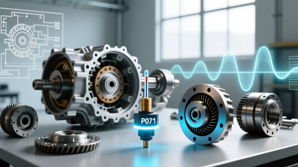
Swapping parts based on a generic OBD2 code is a gamble. To definitively diagnose a faulty transmission range sensor, professional transmission builders use a digital storage oscilloscope (DSO) like a PicoScope to graph the sensor's output in real-time. Most modern TR sensors output a 4-bit Gray code or a multiplexed PWM signal rather than a simple analog voltage.
Pro-Tuner Insight: When diagnosing a GM 6L80 IMS, back-probe the four signal wires at the TCM connector. As you slowly move the shifter from Park to Low, you should see a clean, digital square-wave transition on your scope. Any 'dropouts' or noisy spikes during the transition indicate worn internal carbon wipers, confirming the sensor must be replaced before attempting any TCM tuning.
Performing a voltage drop test across the sensor's ground circuit is equally vital. A voltage drop greater than 0.1V on the sensor ground wire will skew the 5V reference signal, tricking the TCM into reading an invalid gear position. Always verify chassis and engine block grounds before condemning the sensor.
Performance Upgrades: OEM vs. Heavy-Duty Replacements
When upgrading a transmission for high-horsepower applications, the physical integrity of the range sensor becomes a priority. Aftermarket ratchet shifters and manual shift linkages often exert excessive lateral force on the shift shaft, which can bind the internal detent spring and prematurely wear the TR sensor's internal contacts.
GM 6L80 / 6L90 Internal Mode Switch (IMS)
The factory AC Delco IMS (Part # 24253111) is generally robust, costing between $85 and $120. However, when installing a manual valve body or a high-stall torque converter setup, precision alignment is non-negotiable. Performance builders often machine the shift shaft detent to reduce side-loading on the IMS wiper arm, extending the life of the sensor under aggressive track use.
Ford 10R80 Lead Frame Assembly
In the Ford 10R80, the TR sensor is not a standalone component; it is molded into the internal wiring harness and lead frame (Ford Part # ML3Z-7A103-A, retailing around $350). If the Hall-effect range sensor fails, the entire lead frame must be replaced. Upgrading to the latest revision of the Ford lead frame is highly recommended for 2018-2020 models, as early versions were prone to micro-cracking in the PCB traces due to thermal expansion.
ZF 8HP Mechatronic Integration
For ZF 8HP platforms, a faulty transmission range sensor usually dictates a complete Mechatronic unit replacement (ZF Part # 1068.298.035), which can exceed $1,800. However, specialized electronics repair shops now offer micro-soldering services to replace the surface-mount Hall-effect sensors on the Mechatronic PCB for a fraction of the cost, provided the valve body bores and solenoids are still in spec.
TCM Recalibration: Mapping the Gray Code
Replacing the physical sensor is only half the battle in a performance build. The TCM must be recalibrated to recognize the new sensor's voltage thresholds, especially if you are using an aftermarket shifter that alters the mechanical throw angles. Using software like the HP Tuners VCM Editor, tuners can access the 'Transmission > Gear Command' and 'Range Sensor' tables.
Below is the standard 4-bit Gray code voltage mapping for a properly calibrated GM 6L80 IMS. Deviations from these baseline values will trigger a P0706 (Range/Performance) code and force the TCM into limp mode.
| Gear Position | Signal A (Volts) | Signal B (Volts) | Signal C (Volts) | Signal D (Volts) | TCM Interpretation |
|---|---|---|---|---|---|
| Park (P) | 0.0V | 0.0V | 0.0V | 0.0V | Valid Park / Starter Enable |
| Reverse (R) | 5.0V | 0.0V | 0.0V | 0.0V | High Line Pressure Apply |
| Neutral (N) | 0.0V | 5.0V | 0.0V | 0.0V | Valid Neutral / Starter Enable |
| Drive (D) | 5.0V | 5.0V | 0.0V | 0.0V | Standard Shift Scheduling |
| Low (L/M) | 0.0V | 0.0V | 5.0V | 0.0V | Tow/Haul or Manual Tap Mode |
When tuning, ensure that the 'Invalid Gear' timeout parameters are adjusted. In high-vibration race applications, momentary signal dropouts between gears can cause the TCM to command neutral, resulting in catastrophic engine over-revving. Extending the invalid gear delay from the factory 0.2 seconds to 0.5 seconds provides a buffer for mechanical linkage slop without triggering a limp-mode event.
Installation Best Practices and Torque Specifications
Proper installation of the TR sensor or IMS is critical to prevent immediate failure. The alignment pin on the sensor must perfectly match the neutral detent on the transmission shift shaft.
- Verify Neutral Alignment: Rotate the shift shaft clockwise to the Park position, then click it counter-clockwise exactly two detents to find true Neutral. Align the sensor's neutral mark (usually a small notch or line) with the case reference point.
- Fastener Torque: For the GM 6L80 IMS, the retaining bolt must be torqued to exactly 10 Nm (89 lb-in). Over-torquing will crack the plastic sensor housing, allowing transmission fluid to infiltrate the electrical contacts and cause an immediate short circuit.
- Connector Seating: Apply a small amount of dielectric grease to the TCM harness connector. Ensure the weather-pack seal is fully seated to prevent moisture ingress, which is a leading cause of P0707 (Low Input) codes in track-driven vehicles.
- Linkage Adjustment: Reconnect the shift linkage and verify that the detent spring provides firm, positive engagement into each gear. A loose linkage will cause the sensor wiper to rest between contacts, generating excessive heat and resistance.
Conclusion
A faulty transmission range sensor is a critical failure point that can completely undermine an otherwise flawless transmission build or TCM tune. By understanding the underlying electronic control architecture, utilizing oscilloscope diagnostics, and adhering to strict torque and recalibration protocols, you can ensure that your transmission's hydraulic and electronic systems operate in perfect harmony. Whether you are upgrading a 6L80 for a drag car or repairing a ZF 8HP Mechatronic for a street/track build, precision in the range sensor circuit is the key to reliable, high-performance shifting.