The Intersection of Engine Cooling and Transmission Electronics
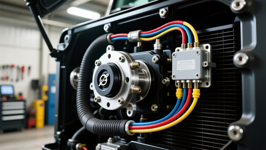
When fleet technicians and owner-operators search for the Volvo VNL fan clutch solenoid location, they are typically troubleshooting an engine cooling fault, a derate condition, or a viscous fan engagement issue. On the prevalent Volvo D11 and D13 engines, this electro-pneumatic solenoid is mounted directly on the front gear train cover, usually on the passenger side near the AC compressor and belt tensioner assembly. However, what many technicians overlook is the critical wiring backbone that routes from this front-engine area, down the side of the block, and directly over the transmission bell housing.
This shared harness pathway is the central nervous system for both engine cooling and heavy-duty transmission sensor wiring. Whether your Volvo VNL is equipped with the automated I-Shift (AT2612D) or an Allison 4000 series automatic, the wiring harnesses for the transmission Input Speed Sensor (ISS) and Output Speed Sensor (OSS) are often bundled, zip-tied, or loomed alongside the engine fan clutch and coolant temperature circuits. As of 2026, with heavy-duty telematics and J1939 CAN bus networks operating at higher data densities, preventive maintenance on these shared transmission sensor connectors is no longer optional—it is mandatory to prevent catastrophic limp-mode events.
Heavy-Duty Transmission Sensor Wiring Architecture
Understanding the physical layout of the harness is the first step in a robust preventive maintenance (PM) program. The main engine-to-chassis harness drops behind the D13 engine block, passing the bell housing where the transmission speed sensors reside. These sensors utilize shielded twisted pair (STP) wiring, typically 18 AWG TXL (cross-linked polyethylene), to transmit high-frequency AC voltage or digital square wave signals back to the Transmission Control Module (TCM).
Because the Volvo VNL fan clutch solenoid location places it in a high-vibration, high-heat zone, the downstream harness routing is subjected to severe thermal cycling and harmonic vibration. This environment accelerates two primary failure modes in transmission sensor wiring:
- Micro-Fretting Corrosion: Vibration causes microscopic movement between the male and female pins inside the Deutsch DT or Weather-Pack connectors, wearing away the tin or gold plating and creating high-resistance oxide layers.
- Insulation Chafing: The STP shielding rubs against the cast-iron transmission bell housing or aluminum air compressor mounts, eventually grounding the signal wire and triggering false speed readings.
Preventive Maintenance: Connector Inspection and Rehabilitation
A proper PM schedule for transmission sensor wiring must go beyond a simple visual check. Technicians must physically disconnect, clean, and re-seal the connectors. According to guidelines from the SAE International J1939 network standards, maintaining pin integrity is vital for preventing CAN bus voltage drops that lead to ghost codes.
Step-by-Step Connector Rehab Protocol
- Safe Disconnect: Never pull on the wires. Depress the primary locking tab, then use a specialized connector puller or gentle twisting motion to separate the Deutsch DT or Ampseal housings.
- Chemical Cleaning: Spray both male and female contacts with a high-purity electronics cleaner (e.g., CRC QD Electronic Cleaner or Brakleen Non-Chlorinated). Avoid compressed air, which can drive moisture deeper into the pin barrels.
- Seal Inspection: Check the silicone peripheral seals and the individual wire cavity plugs. If the silicone is flattened, torn, or showing signs of heat blistering, the connector housing must be replaced.
- Dielectric Application: Apply a pea-sized amount of Nyogel 794G or 760G dielectric grease directly to the female pin openings. This specific grease is formulated to dampen vibration and prevent moisture ingress without increasing electrical resistance across the mating surfaces.
Torque Specifications and Pin Retention Data
Improper torque on sensor mounting bolts or harness retention brackets is a leading cause of wire fatigue. When servicing the area around the transmission bell housing, adhere strictly to the following specifications:
| Component / Fastener | Specification / Tool | Torque / Measurement |
|---|---|---|
| I-Shift / Allison Speed Sensor Mounting Bolt (M6x1.0) | 10mm Socket / Beam Torque Wrench | 10 - 12 Nm (89 - 106 lb-in) |
| Bell Housing Harness Retention Bracket | M8 Bolt | 25 Nm (18 lb-ft) |
| Deutsch DT Pin Crimp (Size 16, 18 AWG) | Sargent 1028-CT or Daniels M22520/2-01 | Pull Test: 45 lbs minimum |
| Ampseal 35-Pin TCM Connector Bolts | 5mm Hex / Allen | 3.5 Nm (31 lb-in) - Do not overtighten |
| Sensor Air Gap (Where Applicable) | Feeler Gauge | 0.5mm - 1.2mm (Model Dependent) |
Diagnosing Harness Chafing and J1939 CAN Bus Faults
When transmission sensor wiring fails, the TCM interprets the erratic signals as mechanical slip or component failure, immediately commanding a limp-home mode. Because the harness routing near the Volvo VNL fan clutch solenoid location is tightly packed, chafing is common. Look for the following diagnostic trouble codes (DTCs) and SAE SPNs (Suspect Parameter Numbers):
- P0715 / SPN 191 (Input/Turbine Shaft Speed Sensor Circuit): Often caused by a broken STP shield wire or a corroded Pin A on the ISS connector.
- P0720 / SPN 190 (Output Speed Sensor Circuit): Frequently traced to harness chafing against the transmission crossmember or parking brake cable bracket.
- U0101 (Lost Communication with TCM): If the main Ampseal connector suffers from micro-fretting on the CAN-High or CAN-Low pins (typically Pins 12 and 13), the entire transmission will drop off the J1939 network.
Expert Insight: Never use a standard multimeter to test CAN bus wiring for continuity while the system is powered. Use a digital storage oscilloscope (DSO) to view the square wave output of the speed sensors while the truck is on a dyno or during a low-speed road test. A healthy heavy-duty speed sensor will show a clean, uniform AC sine wave or 5V square wave that increases in frequency proportionally with shaft RPM.
2026 Part Numbers, Repair Kits, and Procurement Costs
Sourcing OEM or high-quality aftermarket equivalents is critical. Cheap, non-OEM pigtails often use inferior potting compounds that melt under the hood of a Class 8 truck. Below is a procurement guide for common transmission sensor wiring components associated with the Volvo VNL and heavy-duty Allison/I-Shift platforms:
| Component Description | Part Number (Ref) | Est. Cost (2026) |
|---|---|---|
| Volvo I-Shift Input Speed Sensor | 85018058 / 20395185 | $145 - $180 |
| Allison 4000 Series Output Speed Sensor | 29543254 | $110 - $135 |
| Deutsch DT 2-Pin Plug & Receptacle Kit | DT06-2S / DT04-2P | $4.50 - $6.00 |
| TE Connectivity Ampseal 35-Pin Seal | 776273-1 | $12.00 - $18.00 |
| Nyogel 794G Dielectric Grease (20g Tube) | 794G-20 | $22.00 - $28.00 |
Advanced Wiring Repair: Heat Shrink and Soldering
If you discover broken wires within 6 inches of the transmission sensor connector, do not simply twist and tape them. The TE Connectivity DEUTSCH engineering guidelines strictly recommend against twisting wires in high-vibration environments. Instead, use a staggered solder-seal heat shrink kit (e.g., Raychem SolderSleeve). Staggering the splices prevents a single bulky node from forming inside the harness loom, which can create a pressure point against the transmission casing and lead to future chafing.
Summary: Integrating Sensor Wiring into Fleet PM Schedules
Locating the Volvo VNL fan clutch solenoid location is just the beginning of a comprehensive under-hood and bell-housing inspection. Fleet managers should mandate a transmission sensor wiring and connector PM every 150,000 miles or annually, whichever comes first. This service must include disconnecting the ISS and OSS sensors, inspecting the STP shielding for ground faults, cleaning the Deutsch pins, and applying fresh dielectric grease. By treating the transmission sensor harness with the same respect as the engine's primary fuel and cooling systems, fleets can eliminate thousands of dollars in unnecessary tow bills and TCM replacement costs caused entirely by a $4 corroded connector.
For further reading on heavy-duty electrical standards and J1939 network topologies, refer to the Volvo Trucks North America Service Portal and your specific chassis manufacturer's wiring schematics.