The Intersection of Pneumatics and Electronic Control Systems
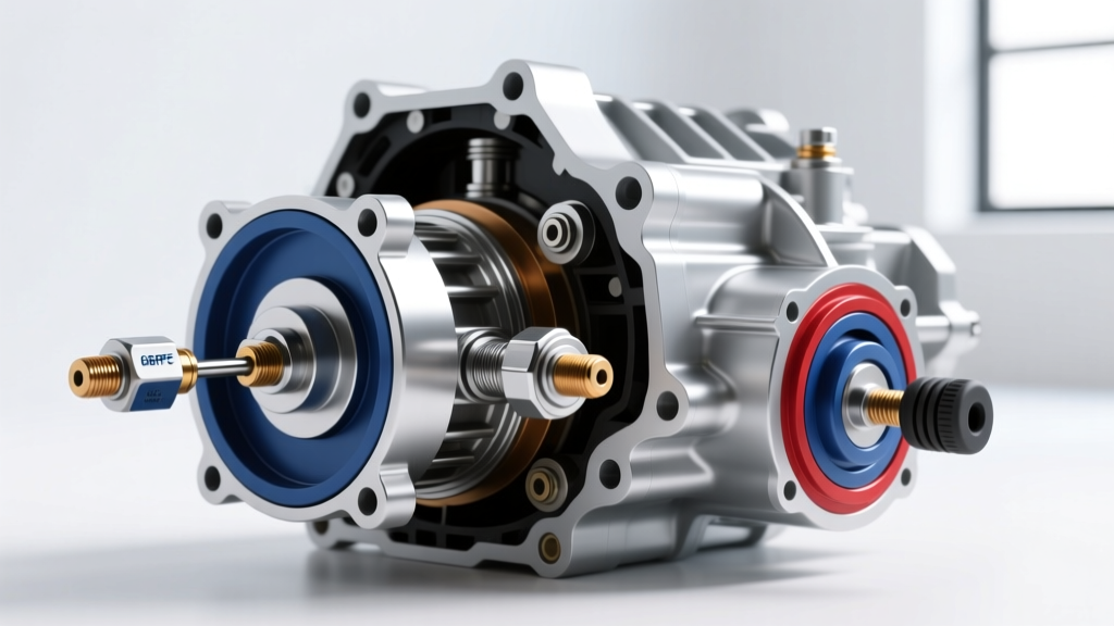
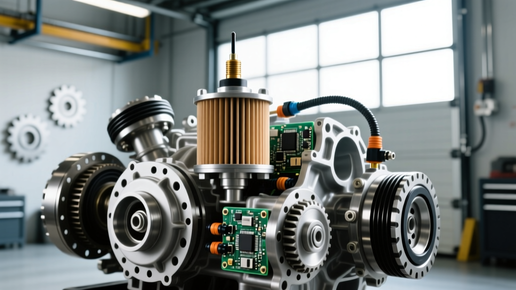
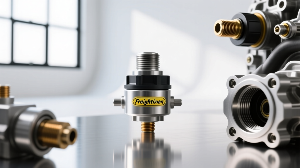
In the modern heavy-duty trucking landscape of 2026, Automated Manual Transmissions (AMTs) have completely dominated the market. For the Freightliner Cascadia, the Detroit DT12 and Eaton UltraShift PLUS transmissions rely on a complex symbiosis between high-voltage electronic control modules and high-pressure pneumatic actuation. While technicians frequently diagnose shift solenoids and speed sensors, the pneumatic feedback loop is equally vital. At the heart of this loop is the freightliner cascadia transmission air pressure sensor, a critical transducer that dictates whether the Transmission Control Module (TCM) will authorize a gear change or trigger a derogation limp mode.
Upgrading and optimizing this sensor—and its associated air delivery subsystem—is one of the most effective performance modifications a fleet manager or owner-operator can make to reduce shift lag, prevent clutch glazing, and eliminate phantom neutral faults. This guide explores the deep technical specifications, diagnostic protocols, and performance upgrades for the Cascadia’s AMT air pressure monitoring systems.
Pneumatic-Electronic Symbiosis: Why Air Pressure Dictates Shift Quality
Unlike passenger vehicle automatics that rely on hydraulic fluid pressure from a mechanical pump, heavy-duty AMTs like the Detroit DT12-1750-OHE use the vehicle’s onboard air brake system to actuate the clutch and shift rails. The TCM requires real-time verification of air reservoir pressure before initiating a shift sequence. If the system pressure drops below the critical threshold—typically 85 PSI (5.8 bar) for clutch actuation and 75 PSI for gear rail engagement—the TCM will inhibit upshifts to prevent the transmission from falling into a false neutral, which could result in catastrophic driveline shock or loss of motive power on a grade.
The air pressure sensor is a piezoresistive transducer. It converts mechanical pneumatic force into an analog voltage signal (typically 0.5V to 4.5V) that the TCM reads via a 12-bit Analog-to-Digital Converter (ADC). In performance applications, such as heavy-haul or steep-grade logging operations, the demand for rapid, consecutive downshifts can cause momentary pressure drops. Upgrading to a high-flow sensor and optimizing the pneumatic feed line ensures the TCM receives instantaneous, noise-free data, allowing for aggressive shift mapping without triggering false low-pressure fault codes.
OEM vs. Heavy-Duty Performance Sensors: Component Breakdown
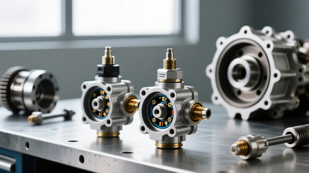
When sourcing a replacement or planning an upgrade, understanding the hardware differences between standard OEM replacements and heavy-duty performance variants is crucial. Below is a comparison matrix based on 2026 fleet maintenance data and component teardowns.
| Specification | OEM Detroit / WABCO Standard | Heavy-Duty Performance Variant |
|---|---|---|
| Part Number | A0615402218 / 4410400140 | BorgWarner HV-Transducer 8800X |
| Operating Range | 0 - 150 PSI | 0 - 200 PSI (Burst rated to 450 PSI) |
| Response Time | < 5 milliseconds | < 1.5 milliseconds |
| Diaphragm Material | Standard Stainless Steel | Hastelloy C-276 (Corrosion Resistant) |
| Average Cost (2026) | $145 - $175 | $190 - $230 |
For standard over-the-road fleets, the OEM Detroit Diesel DT12 sensor is perfectly adequate. However, for severe-duty applications where compressor oil carryover and moisture contamination are prevalent, the Hastelloy diaphragm in the performance variants prevents the micro-pitting that leads to signal drift and eventual sensor failure.
J1939 CAN Bus Diagnostics and Fault Code Matrix
In the SAE J1939 CAN bus architecture, the transmission air pressure sensor data is broadcast across the network, primarily monitored by the TCM and the Engine Control Module (ECM) for torque-limiting requests during shifts. When diagnosing shift complaints, technicians must look beyond standard OBD-II P-codes and utilize heavy-duty diagnostic software (like Detroit DiagnosticLink or Eaton ServiceRanger) to read J1939 Suspect Parameter Numbers (SPN) and Failure Mode Identifiers (FMI).
Critical SPN/FMI Combinations for Air Pressure
- SPN 520604 / FMI 3 (Voltage Above Normal): Indicates an open circuit on the sensor ground or a short to the 5V reference. The TCM reads a solid 4.8V+ and assumes maximum pressure, which can lead to dangerous clutch slip if actual air pressure is low.
- SPN 520604 / FMI 4 (Voltage Below Normal): Indicates a short to ground or internal sensor diaphragm failure. The TCM reads <0.2V, instantly triggering a limp-in mode and inhibiting all automated shifts.
- SPN 520604 / FMI 0 (Data Valid but Above Maximum): The sensor is functioning, but system pressure is exceeding safe limits (e.g., governor failure on the air compressor), risking blown pneumatic actuator seals.
- SPN 520604 / FMI 1 (Data Valid but Below Minimum): The sensor is reading accurately, but the air supply system cannot maintain the 85 PSI minimum threshold during rapid shifting sequences.
Oscilloscope Signal Analysis: Beyond the Multimeter
Using a standard digital multimeter (DMM) to check the 5V reference and ground is only the first step. To truly evaluate the health of the freightliner cascadia transmission air pressure sensor, performance technicians use an automotive oscilloscope to monitor the analog signal wire under load. A healthy sensor will show a smooth, linear voltage climb as the air compressor builds pressure. If the oscilloscope reveals 'stair-step' voltage jumps or high-frequency AC noise superimposed on the DC signal, the sensor's internal Wheatstone bridge is degrading, or the 5V reference line is suffering from Electromagnetic Interference (EMI) generated by the alternator or high-current starter cables.
Voltage to PSI Mapping Table
| Signal Voltage | Calculated Pressure | TCM Action State |
|---|---|---|
| 0.50V | 0 PSI | System Empty / Fault Inhibit |
| 1.83V | 40 PSI | Clutch Brake Inhibited |
| 3.16V | 80 PSI | Marginal / Shift Delay Logic Active |
| 3.50V | 90 PSI | Normal Shift Authorization |
| 4.50V | 120 PSI | Optimal Performance / Full Flow |
Performance Installation and Torque Specifications
Improper installation of pneumatic sensors is a leading cause of micro-leaks and thread stripping on the aluminum transmission shift tower housings. Follow this exact protocol for sensor replacement and upgrade:
- System Depressurization: Drain all primary and secondary air reservoirs. Verify zero PSI on the dash gauges and manually pull the parking brake valves to bleed trapped air from the AMT actuator lines.
- Electrical Disconnect: Disconnect the 3-pin Deutsch-style or Weather-Pack connector. Inspect the pins for green copper oxide corrosion. Apply dielectric grease (Part # 19207762) to the connector seal before reassembly.
- Removal: Use a deep-wall 6-point socket to remove the sensor. Avoid open-end wrenches which can round the sensor hex and damage the internal piezoresistive crystal.
- Thread Preparation: The OEM thread is typically M12x1.5. Clean the female threads in the shift tower block with an M12x1.5 bottoming tap. Never use standard PTFE thread tape, as shredded tape can enter the pneumatic orifice and block the pilot valve in the shift actuator.
- Sealing: Apply a single drop of liquid PTFE thread sealant (e.g., Loctite 565) to the sensor threads, or use a new OEM copper crush washer if the sensor design dictates a straight-thread O-ring/boss (ORB) seal.
- Torque Specification: Torque the sensor to exactly 22 Nm (16 lb-ft). Over-torquing will crack the sensor housing or distort the shift tower aluminum, leading to slow air leaks that trigger SPN 520604 FMI 1 codes under heavy braking.
Upgrading the Air Delivery Subsystem for Faster Shifts
Replacing the sensor alone will not fix slow shift times if the pneumatic delivery system is restricted. According to WABCO Air Management Systems engineering bulletins, the volume of air and the speed at which it reaches the sensor and actuator dictate shift firmness. To build a true performance AMT air system, implement the following upgrades:
- PTFE-Lined Stainless Braided Hoses: Replace the OEM 3/8-inch nylon push-to-connect air lines feeding the transmission with 1/2-inch PTFE-lined stainless braided hoses. This increases air volume flow by 78% and eliminates the 'ballooning' effect seen in nylon lines under high-pressure spikes, ensuring the TCM sensor reads instantaneous pressure changes.
- High-Flow Relay Valves: Install a high-flow WABCO relay valve at the main air tank dedicated to the AMT. This ensures that when the TCM commands a clutch actuation, the air is sourced locally at the transmission rather than traveling 15 feet from the dash-mounted treadle valve.
- Shielded Wiring Harness: Route the sensor wiring harness away from the starter motor and alternator. If EMI noise is detected on the oscilloscope, splice in a Shielded Twisted Pair (STP) cable for the 5V reference and signal wires, grounding the shield at the TCM connector only to prevent ground loops.
- Upstream Filtration: Install a coalescing air filter (0.01 micron) between the air dryer and the AMT supply line. This prevents compressor oil aerosols from coating the sensor diaphragm, a common issue highlighted in TruckingInfo's AMT Maintenance Guide, which causes the sensor to read sluggishly and delays TCM shift commands.
Conclusion: The ROI of Sensor Optimization
In the highly competitive logistics environment of 2026, a delayed shift equates to lost momentum, increased fuel consumption, and accelerated clutch wear. The freightliner cascadia transmission air pressure sensor is not merely a passive monitoring device; it is the primary gatekeeper for the TCM's shift logic. By upgrading to heavy-duty transducers, optimizing the pneumatic feed lines, and utilizing oscilloscope-level diagnostics, fleets can drastically reduce transmission-related road calls and ensure the Detroit DT12 operates with the precision and speed it was engineered to deliver.