From Robotics to the Road: The Engineering Leap
In the 2026 landscape of automotive engineering and STEM education, many future technicians and engineers cut their teeth on the modular VEX V5 drivetrain. Building a competition robot teaches foundational concepts of gear reduction, traction, and torque distribution. However, transitioning from a robotics platform to diagnosing real-world automotive Front-Wheel Drive (FWD) system operation requires a massive paradigm shift. A VEX V5 Smart Motor outputs roughly 11 watts of continuous power; a modern 2.0L turbocharged FWD transaxle manages upward of 150 kilowatts (200+ hp) while mitigating extreme thermal loads, dynamic suspension articulation, and NVH (Noise, Vibration, and Harshness) requirements.
This guide bridges that gap, utilizing the analytical mindset fostered by robotics to diagnose complex automotive FWD symptoms, from CV joint failure to transaxle torque steer.
Architectural Scaling: VEX V5 Drivetrain vs. Automotive FWD
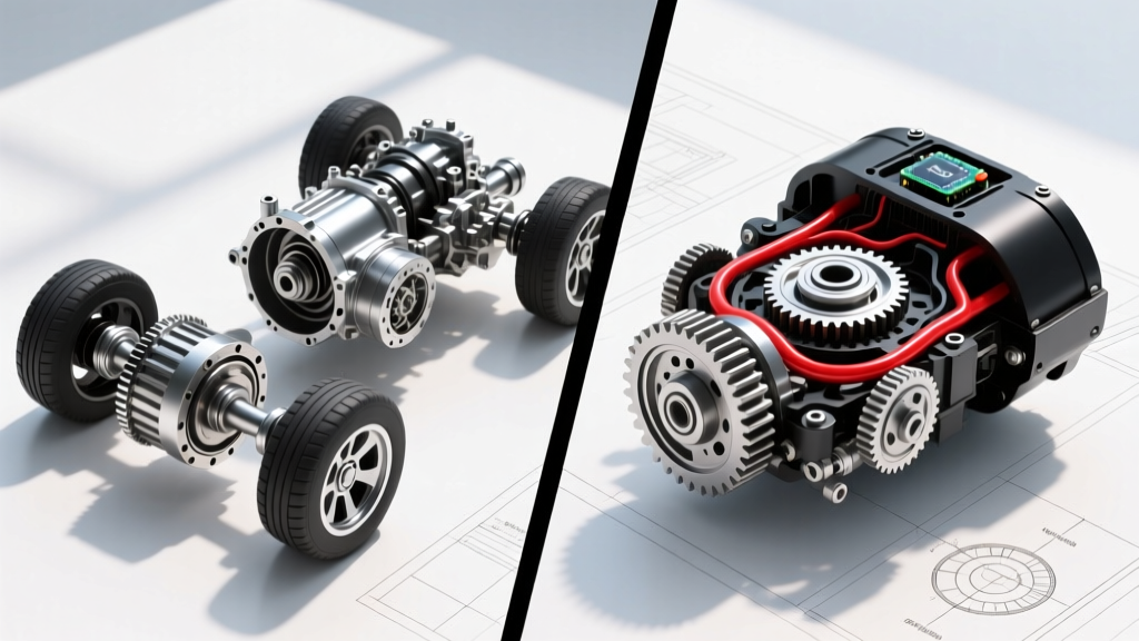
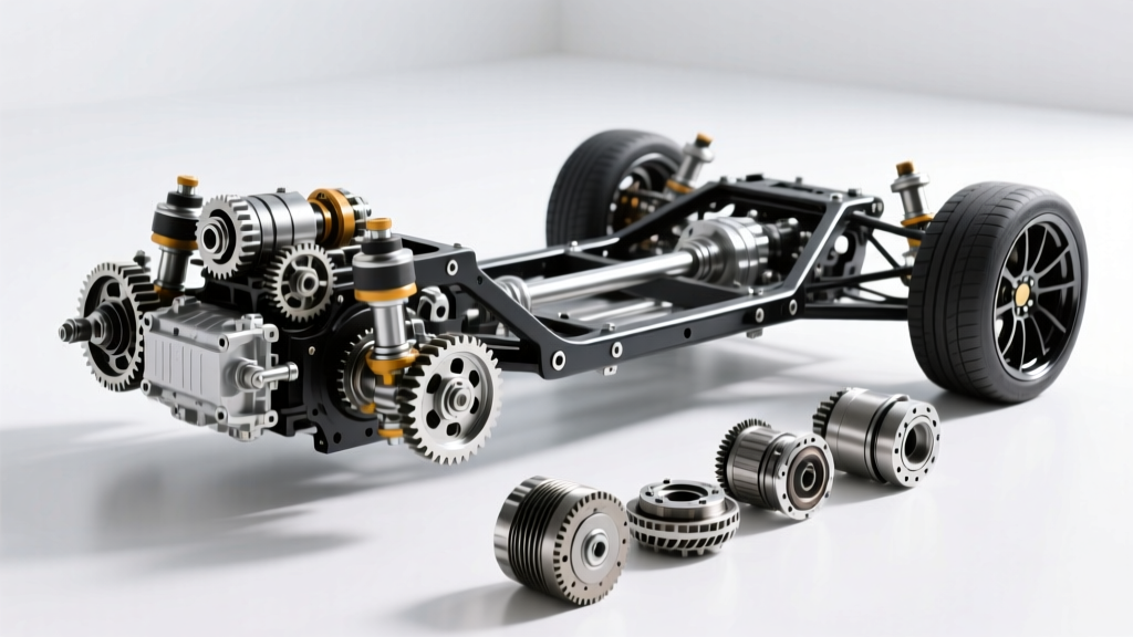
Before pulling out a scan tool or a pry bar, it is crucial to understand how power delivery scales from a modular robotics chassis to a unibody passenger vehicle. In a VEX V5 system, drivetrains typically utilize direct-chain, spur gear, or simple bevel gear differentials enclosed in lightweight polycarbonate or aluminum brackets. Automotive FWD integrates the transmission and differential into a single transaxle casing, relying on complex constant velocity (CV) axles to route power through steering knuckles that articulate in three dimensions.
| Parameter | VEX V5 Drivetrain (Robotics) | Automotive FWD (e.g., GM 6T40 / Honda HA) |
|---|---|---|
| Power Output | 11W per motor (Max 88W / 8 motors) | 110kW - 160kW (150 - 215 hp) |
| Differential Type | Open spur gear / locked spool | Hypoid bevel gear with clutch packs (LSD) or open |
| Axle Articulation | Rigid shafts, zero suspension travel | Rzeppa/Tripod CV joints (Up to 47° steering angle) |
| Lubrication | Light PTFE grease / dry bearings | 75W-90 Gear oil / Dexron VI ATF (8.0L capacity) |
Symptom Diagnosis 1: Clicking, Popping, and Binding on Turns
The most common FWD drivetrain complaint is a rhythmic clicking or popping noise during tight, low-speed turns. While a robotics drivetrain might skip a tooth on a worn chain drive under load, an automotive FWD system suffers from Outer CV Joint (Rzeppa Joint) Degradation.
The Failure Mechanism
The outer CV joint houses six steel ball bearings riding in a cage and inner race. These are packed with a specific molybdenum disulfide (MoS2) grease. When the thermoplastic CV boot tears due to dry rot, road debris, or heat from nearby exhaust components, moisture enters and grease escapes. The resulting metal-on-metal wear creates pitting on the ball bearings and the raceway grooves.
Actionable Troubleshooting & Repair Specs
- Visual Inspection: Check the inner ridges of the CV boot for grease slinging. A torn boot requires immediate replacement to save the joint if caught early.
- Test Drive: Perform full-lock figure-eight maneuvers in an empty lot. A clicking noise that speeds up with vehicle speed (not engine RPM) isolates the outer CV joint.
- Hardware Note: Never reuse a stretched axle nut. For a common GM midsize platform (e.g., Malibu 1.5T), the replacement axle nut (Part # 11569842, M12x1.5) requires a massive 260 Nm (192 lb-ft) of torque, followed by staking the collar into the shaft groove.
- Cost Expectation: OEM half-shaft assemblies range from $250 to $450. Avoid cheap aftermarket remanufactured shafts, as they often suffer from harmonic vibrations at highway speeds due to poor dynamic balancing.
Symptom Diagnosis 2: Highway Speed Driveline Shudder
If a vehicle exhibits a lateral shudder or vibration specifically between 60 and 80 mph under light acceleration, the issue is rarely wheel balance. In the FWD layout, this points directly to the Inner CV Joint (Tripod Joint) or the Intermediate Shaft Carrier Bearing.
Inner Tripod Wear
Unlike the ball-type outer joint, the inner joint uses a tripod design with three roller bearings on needle caps. These allow for the in-and-out plunging motion required as the suspension compresses and rebounds. Over 100,000 miles, the needle bearings can develop flat spots, or the tripod housing wears into an oval shape. Under load, the rollers bind instead of plunging smoothly, transmitting a low-frequency lateral shake through the chassis.
The Intermediate Shaft Factor
To combat torque steer, many FWD vehicles (notably Honda and Ford platforms) use an intermediate shaft on the passenger side to equalize the length of the left and right half-shafts. This shaft is supported by a carrier bearing bolted to the engine block.
Diagnostic Step: With the vehicle on a lift and the suspension loaded, use a stethoscope to listen to the intermediate shaft carrier bearing (e.g., Honda Part # 91205-TR0-A01) while an assistant revs the engine in gear. A growling or grinding noise confirms bearing failure. Replacement requires draining the transaxle fluid, as the intermediate shaft passes directly through the differential side seal.
Symptom Diagnosis 3: Torque Steer and Bushing Compliance
In a VEX V5 drivetrain, torque steer is virtually non-existent due to the low power output and rigid chassis. In a 300-hp FWD hot hatch, torque steer is a constant battle. When a driver mashes the throttle and the steering wheel violently pulls to one side, the root cause is often misdiagnosed as a differential issue. In reality, it is a suspension compliance failure.
Hydraulic Lower Control Arm Bushings
Modern FWD vehicles utilize fluid-filled hydraulic bushings in the rear position of the lower control arms to absorb road impacts. When these bushings tear or leak their glycol fluid, the control arm shifts backward under acceleration. This alters the dynamic toe and camber of the front wheels, causing the steering axis to pull aggressively toward the side with the most compliance or grip.
- The Pry-Bar Test: Insert a large pry bar between the subframe and the lower control arm. If the bushing exhibits more than 3-4mm of deflection or shows visible cracking/fluid weeping, replacement is mandatory.
- Alignment Specs: Always follow bushing replacement with a precise four-wheel alignment. Ensure the steering axis inclination (SAI) is equal side-to-side; unequal SAI indicates a bent strut or spindle, which will perpetuate torque steer regardless of new bushings.
Transaxle Fluid Diagnostics: The Lifeblood of FWD
Unlike a robotics gear case that is sealed for life with a dab of white lithium grease, an automotive transaxle relies on specialized Automatic Transmission Fluid (ATF) to lubricate hypoid gears, actuate clutch packs, and cool the torque converter. According to SAE International standards, fluid shearing is a primary cause of premature FWD transaxle failure.
Diagnostic Fluid Analysis
Pull the transaxle dipstick or crack the drain plug to evaluate the fluid condition:
- Cherry Red & Sweet: Healthy fluid. Standard service interval applies.
- Dark Brown & Burnt Smell: Friction material from the clutch packs is degrading. The transaxle is slipping, generating excess heat. A fluid flush will not fix worn clutches; a rebuild or replacement is imminent.
- Glitter / Metallic Flakes: Planetary gearset or differential bearing failure. The fluid is contaminated with ferrous metals. Immediate teardown is required.
Expert Tip: For the ubiquitous GM 6T40 6-speed transaxle, the dry-fill capacity is 8.0 Liters, but a standard drain-and-fill only yields about 5.0 Liters. Always use the precise OEM fluid (e.g., ACDelco Dexron VI, Part # 10-9395). Using generic 'multi-vehicle' ATF can cause erratic shift solenoid operation and torque converter shudder due to incompatible friction modifiers.
Summary: Applying Engineering Logic to the Garage
Whether you are optimizing a VEX V5 drivetrain for a robotics competition or diagnosing a shuddering CV axle on a daily commuter, the core principles of mechanical engineering remain identical. Power must be transmitted efficiently, heat must be managed, and moving parts must be protected from contamination. By understanding the vast scale difference between modular robotics and automotive transaxles, technicians can move beyond guesswork. Rely on precise torque specifications, systematic load-testing, and fluid analysis to conquer any FWD drivetrain malfunction.
For further certification and diagnostic standards, consult the National Institute for Automotive Service Excellence (ASE) guidelines on Automatic Transmissions and Transaxles (Test A2).