The Anatomy of a Vehicle Differential Rebuild
Rebuilding a solid-axle vehicle differential is one of the most rewarding yet unforgiving tasks in automotive drivetrain repair. Unlike swapping a transmission, where tolerances are managed internally by the manufacturer, setting up a ring and pinion requires manual precision down to the thousandth of an inch. A flawed setup will result in catastrophic gear failure, excessive whining, or premature bearing wear within the first 1,000 miles.
Whether you are refreshing a worn-out Ford 8.8-inch, a classic Dana 44, or a GM 10-bolt, the fundamental physics of hypoid gear mesh remain identical. This step-by-step guide details the exact procedures, torque specifications, and diagnostic frameworks required to execute a professional-grade vehicle differential rebuild.
Phase 1: Procurement and Essential Tooling
Before unbolting the differential cover, you must assemble the correct metrology tools. Guessing shim thicknesses by hand is a guaranteed path to failure.
- Dial Indicator & Magnetic Base: Mitutoyo 2046S (0.001-inch resolution) for measuring backlash and side bearing preload.
- Inch-Pound Torque Wrench: A beam-style or high-resolution click-type inch-pound wrench (e.g., Intercomp 101-1650) to measure pinion rotating torque.
- Bearing Puller & Hydraulic Press: Essential for removing and installing pinion and carrier bearings without damaging the cages.
- Gear Marking Compound: Yellow ochre or specialized hypoid gear paste to read the contact pattern.
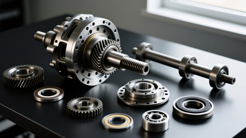
- Master Rebuild Kit: Always use Timken or Koyo bearings. Cheap offshore bearing kits often have out-of-spec races that ruin pinion depth calculations. Expect to spend $150–$220 for a quality master kit (e.g., Yukon Gear YK KIT-F8.8).
Phase 2: Teardown and Housing Inspection
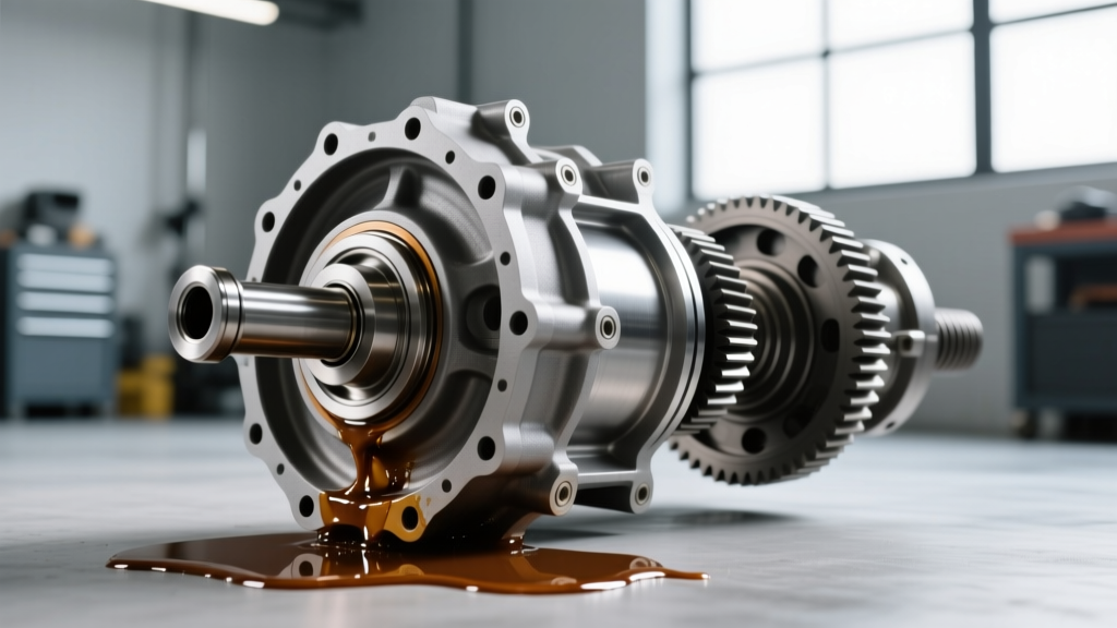
Drain the gear oil and inspect it immediately. Fine metallic paste on the drain plug magnet is normal wear; however, chunky ferrous shards or brass-colored flakes indicate catastrophic bearing or spider gear failure.
Marking and Extraction
Before removing the bearing caps, use a stamping die to mark the left and right caps. Differential bearing caps are line-bored at the factory with the housing. Mixing them up will cause severe side-bearing misalignment and immediate gear destruction. Once the caps are removed, extract the carrier and use a puller to remove the pinion gear from the housing.
Case Bore Inspection
Use a dial bore gauge to check the carrier bearing bores. If the housing is stretched beyond 0.002 inches out of round—common in high-horsepower drag applications or heavily abused off-road rigs—the housing must be line-honed or replaced before proceeding.
Phase 3: Setting Pinion Depth and Preload
The pinion depth is the most critical measurement in any vehicle differential rebuild. It dictates how deeply the pinion gear sits relative to the ring gear centerline.
Calculating the Depth Shim
Most ring and pinion sets feature a laser-etched variance code on the pinion head (e.g., "+2" or "-1"). This number represents the deviation from the nominal factory housing depth, measured in thousandths of an inch. If your original pinion was marked "0" and required a 0.035-inch shim, and your new pinion is marked "+2", your new starting shim thickness will be 0.037 inches.
Press the rear pinion bearing onto the pinion shaft, install it into the housing with the calculated shim, and seat the front bearing.
Establishing Pinion Bearing Preload
Pinion preload is the friction required to rotate the pinion shaft without the carrier installed. For axles utilizing a collapsible crush sleeve (like the Ford 8.8 or GM 10-bolt), you must tighten the pinion nut incrementally while checking the rotating torque.
- Target Rotating Torque (New Bearings): 16 to 28 inch-pounds (varies by axle; Ford 8.8 spec is typically 8-14 in-lbs for used bearings, but 16-28 in-lbs for new, dry Timken bearings).
Warning: If you overtighten the crush sleeve, you must replace it. Never back off the pinion nut to reduce preload; doing so compromises the sleeve's structural integrity.
Phase 4: Carrier Setup and Backlash Adjustment
With the pinion set, bolt the ring gear to the carrier. Always use new ring gear bolts and apply red Loctite (271). Torque them in a star pattern. For a Dana 44, the spec is typically 75 ft-lbs; for a GM 12-bolt, it is 120 ft-lbs.
Setting Backlash
Backlash is the rotational play between the ring and pinion teeth. Mount your dial indicator perpendicular to the ring gear teeth. Hold the pinion flange completely stationary and rock the ring gear back and forth.
| Axle Model | Target Backlash | Pinion Preload (New) | Ring Gear Bolt Torque |
|---|---|---|---|
| Ford 8.8-Inch | 0.008" - 0.012" | 16 - 28 in-lbs | 70 - 85 ft-lbs |
| Dana 44 (Standard) | 0.006" - 0.010" | 20 - 30 in-lbs | 70 - 90 ft-lbs |
| GM 10-Bolt (8.5") | 0.006" - 0.010" | 15 - 25 in-lbs | 120 ft-lbs |
| Dana 60 (Front) | 0.006" - 0.011" | 25 - 35 in-lbs | 130 ft-lbs |
Adjust the side bearing shims (or adjuster nuts on Ford/Chrysler axles) until the dial indicator reads within the target specification. If backlash is too tight, move the ring gear away from the pinion; if it is too loose, move it closer. Always maintain total side-bearing preload by adding thickness to one side while removing the exact same amount from the other.
Phase 5: Reading the Contact Pattern
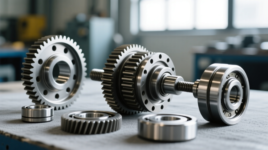
Numbers on a dial indicator only tell half the story. The physical gear contact pattern confirms whether your pinion depth and backlash settings are harmonized. Apply a thin, even coat of yellow gear marking compound to three or four teeth on both the drive (convex) and coast (concave) sides of the ring gear.
Apply moderate rotational resistance to the ring gear using a rag or brake drag, and rotate the pinion flange through the marked teeth in both directions.
Pattern Diagnostics
- Ideal Pattern: Centered vertically between the face (top) and flank (root) of the tooth, and slightly biased toward the toe (inner edge) under load, moving toward the heel (outer edge) when unloaded.
- Toe/Heel Bias: If the pattern is too far toward the toe or heel, adjust the backlash. More backlash moves the pattern toward the heel; less backlash moves it toward the toe.
- Face/Flank Bias: If the pattern rides too high (face) or too low (flank/root), your pinion depth is incorrect. A high pattern requires moving the pinion deeper into the housing (thicker shim); a low pattern requires moving it out (thinner shim).
Expert Insight: According to Randy's Ring & Pinion technical guidelines, the drive side pattern under load is vastly more critical than the coast side. Prioritize the drive side if a perfect compromise cannot be achieved.
Phase 6: Final Assembly and Break-In Protocol
Once the pattern is verified, reinstall the axle shafts, seal the differential cover using RTV silicone (Permatex Ultra Black is highly recommended for oil resistance), and prepare for the fluid fill.
Fluid Selection and Additives
For a standard open differential, a high-quality 75W-90 synthetic gear oil like AMSOIL Severe Gear provides superior shear stability and thermal protection. However, if your vehicle differential utilizes a clutch-type limited-slip differential (LSD), you must add a friction modifier (e.g., Ford XL-3 or equivalent) to prevent clutch chatter during low-speed cornering. Note that Torsen and Detroit Lockers do not require friction modifiers.
The 500-Mile Break-In Rule
New hypoid gears generate immense friction and heat as the microscopic machining marks wear into a mating profile. Spicer/Dana engineering manuals strictly mandate a break-in procedure:
- Drive the vehicle under normal, light-load conditions for the first 150 miles. Avoid highway speeds exceeding 55 MPH.
- Allow the differential to cool completely after every 15-20 miles of initial driving to prevent the gear oil from breaking down and glazing the gear surfaces.
- At 500 miles, drain the differential fluid immediately. You will notice a heavy metallic sheen—this is the lapping compound and break-in wear material.
- Refill with fresh gear oil and additive. The differential is now fully seated and ready for heavy towing or off-road use.
Summary of Rebuild Costs and Considerations
A DIY vehicle differential rebuild typically costs between $350 and $600 in parts (ring and pinion set, master bearing kit, seals, and gear oil). In contrast, professional driveline shops charge between $800 and $1,400 for labor and setup. While the financial savings are significant, the margin for error is zero. Invest in the proper measuring tools, respect the torque specifications, and never rush the break-in process to ensure your differential operates quietly and reliably for the next 150,000 miles.