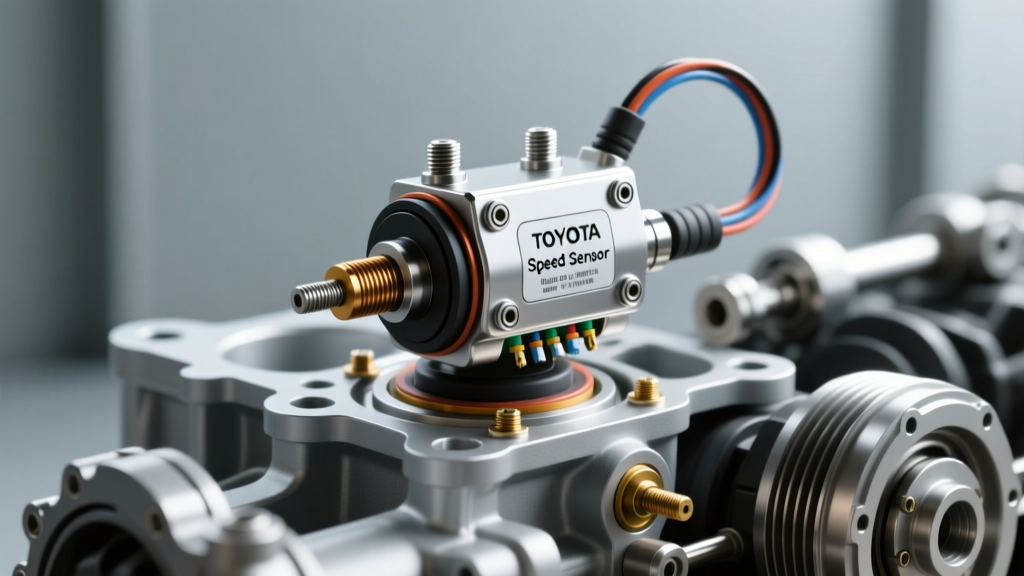
The Diagnostic Trap: Speed Sensors vs. Brake Switches
When a vehicle enters limp mode with a P0717 (Input/Turbine Speed Sensor Circuit No Signal) or P0741 (Torque Converter Clutch System Stuck Off) diagnostic trouble code, the immediate instinct for many technicians is to condemn the transmission speed sensor. However, modern powertrain control modules (PCMs) and transmission control modules (TCMs) rely on a complex network of secondary inputs to validate speed data. One of the most frequently overlooked culprits in erratic speed sensor readings and TCC slip codes is a failing brake differential pressure switch.
As a senior transmission diagnostic specialist, I have seen countless 6L80, 6R80, and ZF 8HP units unnecessarily removed from vehicles because a technician misinterpreted a brake hydraulic pressure signal anomaly as an internal speed sensor failure. In 2026, with the proliferation of high-speed CAN bus networks and advanced torque converter clutch (TCC) slip-control algorithms, understanding the intersection between brake hydraulics and transmission speed data is mandatory for accurate diagnosis.
Understanding the CAN Bus Cross-Talk Phenomenon
The brake differential pressure switch, typically mounted on the master cylinder or brake booster assembly, monitors hydraulic line pressure to detect brake application and brake drag. The TCM uses this data alongside the brake pedal position (BPP) switch to determine when to release the TCC during deceleration.
If the brake differential pressure switch develops an internal short, suffers from moisture ingress, or experiences a voltage drop due to corroded pigtail connectors, it can send erratic, fluctuating pressure signals to the Body Control Module (BCM). Through CAN bus cross-talk, the TCM receives conflicting data: the Output Speed Sensor (OSS) reports 65 MPH, the Input Speed Sensor (ISS) reports 2200 RPM, but the brake pressure switch indicates 400 PSI of hydraulic braking force.
The TCM's fail-safe logic interprets this as a severe mechanical bind or a catastrophic speed sensor signal dropout. It immediately commands maximum line pressure, inhibits TCC lockup, and sets a speed sensor rationality code. Replacing the OSS or ISS in this scenario will not resolve the issue, as the root cause lies entirely outside the transmission casing.
Ruling Out the Brake Differential Pressure Switch
Before unbolting the transmission pan or dropping the extension housing, you must verify the integrity of the brake pressure circuit. Using a bi-directional scan tool (such as an Autel MaxiSys or Snap-on Zeus), monitor the Brake Pressure Sensor PID while an assistant applies and releases the brake pedal.
- Normal Operation: 0-50 PSI at rest, spiking smoothly to 800-1500 PSI under heavy pedal application, returning instantly to baseline upon release.
- Faulty Switch Symptom: Pressure PID hangs at 200+ PSI after pedal release, or exhibits random spikes of 300 PSI while cruising at a steady 60 MPH.
If the PID data is erratic, test the switch's 5V reference, signal return, and low-reference grounds. A failing brake differential pressure switch will often pull the 5V reference circuit down to 2.1V, which can simultaneously corrupt the signal from a shared 5V reference transmission speed sensor on certain Ford and GM architectures.
Oscilloscope Testing: Hall-Effect vs. Variable Reluctance
Once the brake differential pressure switch and CAN network are ruled out, you must physically verify the speed sensor signals. Relying solely on a digital multimeter (DMM) is insufficient for modern diagnostics. An automotive oscilloscope, like those offered in the Pico Technology Waveform Library, is required to visualize the signal integrity under load.
| Sensor Type | Signal Output | Amplitude | Common Applications | Diagnostic Edge Case |
|---|---|---|---|---|
| Hall-Effect (3-Wire) | Digital Square Wave | 0V to 5V / 12V | GM 6L80, Ford 6R80, ZF 8HP | Chipped reluctor wheel causes squared-off waveform drops |
| Variable Reluctance (2-Wire) | AC Sine Wave | 0.5V to 100V+ (Speed Dependent) | Older 4L60E, 5R55W, Allison 1000 | Excessive air gap from metallic debris on sensor tip |
| Magnetoresistive (2-Wire) | Current Modulation | 7mA to 14mA | Mercedes 722.9, ZF 6HP | Requires current clamp; voltage testing yields false failures |
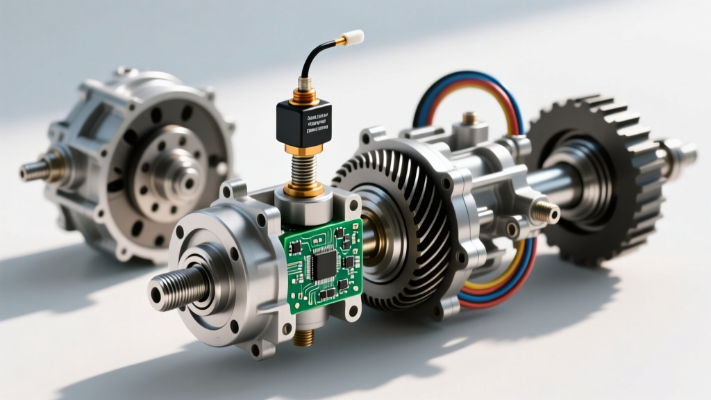
For a 3-wire Hall-Effect OSS on a GM 6L80, connect your oscilloscope to the signal wire. At idle in gear (drive wheels suspended), you should see a clean, crisp 5V square wave. If the waveform shows 'ringing' (voltage overshoot on the rising edge) or intermittent dropouts to 2.5V, you are likely dealing with a damaged internal wiring harness or a cracked solder joint on the sensor's internal PCB, rather than a brake switch issue.
Step-by-Step OSS Replacement: GM 6L80 / 6L90
If your oscilloscope confirms a dead or degraded Output Speed Sensor, replacement on the GM 6L80 and 6L90 platforms is straightforward, provided you adhere to strict torque specifications to prevent case damage or fluid leaks.
Required Tools and Materials
- ACDelco OSS Part Number: 24207054 (Verify with VIN via ACDelco OEM Parts Catalog)
- DEXRON VI Automatic Transmission Fluid (approx. 1.5 quarts for top-off)
- 8mm socket, torque wrench (inch-pounds capable)
- New O-ring seal (usually included with sensor)
Replacement Procedure
- Vehicle Prep: Raise the vehicle on a lift. Remove the necessary skid plates and crossmembers to access the rear extension housing of the transmission.
- Electrical Disconnect: Press the release tab on the OSS connector. Inspect the pigtail for green copper corrosion. If present, cut and splice a new pigtail; do not use contact cleaner alone, as capillary action will draw moisture back into the TCM.
- Sensor Removal: Remove the single 8mm retaining bolt. Gently twist and pull the sensor outward. Warning: Do not pry with a screwdriver, as the aluminum extension housing will gouge, creating a permanent fluid leak path.
- Installation: Lubricate the new O-ring with fresh DEXRON VI fluid. Seat the new sensor fully into the bore.
- Torque Specification: Reinstall the 8mm bolt and torque to exactly 8 Nm (71 lb-in). Over-torquing will strip the aluminum case threads.
- Fluid Level Check: Refill the transmission pan. With the vehicle level and the transmission fluid temperature (TFT) between 95°F and 113°F, check the level plug on the side of the pan until fluid drips out, then reinstall the plug.
The ZF 8HP Mechatronic Reality
Diagnosis shifts dramatically when working on vehicles equipped with the ZF 8HP transmission (found in BMW, Audi, Dodge Ram, and Jaguar models). Unlike the 6L80, the ZF 8HP utilizes speed sensors that are integrated directly into the Mechatronic unit (the combined valve body and TCM).
There is no external OSS or ISS to unbolt. If your oscilloscope confirms an internal speed sensor failure on a ZF 8HP, the entire Mechatronic unit must be replaced or sent to a specialized rebuilder. Furthermore, the brake differential pressure switch plays a vital role in the ZF's 'Stop-Start' and coasting functions. A delayed brake pressure signal will prevent the ZF TCM from executing the rapid hydraulic accumulator pre-fill required for seamless engine restarts, often resulting in harsh engagements that mimic speed sensor miscalibration.
For deep-dive Mechatronic troubleshooting and fluid specifications (ZF LifeguardFluid 8), always consult the ZF Aftermarket Portal for the latest technical service bulletins (TSBs).
Cost and Part Breakdown (2026 Estimates)
Understanding the financial impact of these repairs helps in advising customers accurately. Below is a breakdown of typical costs associated with speed sensor and brake switch diagnostics.
| Component / Service | Part Cost Range | Labor Time | Total Estimated Cost |
|---|---|---|---|
| Brake Differential Pressure Switch | $35 - $85 | 0.5 Hours | $90 - $180 |
| GM 6L80 Output Speed Sensor (OSS) | $40 - $75 | 1.2 Hours | $180 - $320 |
| Ford 6R80 Input Speed Sensor (ISS) | $45 - $90 | 3.5 Hours (Pan Drop) | $450 - $650 |
| ZF 8HP Mechatronic Unit (Reman) | $1,200 - $2,500 | 4.0 Hours + Programming | $2,200 - $4,000+ |
Final Expert Takeaways
Transmission speed sensor diagnosis in modern vehicles is rarely as simple as swapping a part and clearing a code. The integration of chassis control systems, ABS modules, and the brake differential pressure switch into the TCM's decision-making matrix means that a 'transmission' code is often a chassis network fault in disguise.
By utilizing an oscilloscope to verify square-wave integrity, monitoring brake pressure PIDs for hydraulic anomalies, and respecting manufacturer-specific torque specs and fluid levels, you elevate your diagnostic accuracy from guesswork to precision science. Always trace the data, trust the waveform, and never ignore the brake switch.