Completing a DIY transmission cooler install is a massive victory for the longevity of your vehicle. Whether you are towing a heavy camper with a GM 6L80-equipped Silverado, pushing a Ford 10R80 on the highway, or daily-driving a BMW with a ZF 8HP, dropping transmission fluid temperatures by 20 to 40 degrees is the single best modification you can make. However, many enthusiasts treat the installation as the finish line. In reality, the tight engine bays and aggressive thermal cycles of modern 2026 vehicles mean that post-install maintenance is just as critical as the hardware itself.
If you want your auxiliary cooler to perform flawlessly for the next 150,000 miles, you need a proactive maintenance routine. This beginner-friendly guide will walk you through the exact steps, torque specifications, and inspection intervals required to keep your transmission cooling system flowing efficiently and your automatic transmission fluid (ATF) in peak condition.
The Critical First 500 Miles: Bleeding and Break-In
The most vulnerable period for any cooling system is immediately following your transmission cooler install. When you add an external cooler and new lines, you introduce air pockets into the hydraulic circuit. If left unchecked, these pockets can cause erratic line pressure, delayed shifts, and temporary fluid starvation.
Verifying Fluid Levels (Hot vs. Cold)
Modern transmissions are incredibly sensitive to fluid volume. For example, the GM 8L90 and 10L90 series require the fluid to be checked at a specific temperature range—typically between 180°F and 200°F (82°C to 93°C)—using a scan tool to monitor the Transmission Fluid Temperature (TFT) sensor. Checking the dipstick or leveling plug when the fluid is cold will result in severe overfilling once the fluid expands at operating temperature, leading to foaming and aerated fluid hitting your cooler lines.
- Cold Fill: Only use the 'COLD' mark on the dipstick to ensure the pump doesn't cavitate on initial startup.
- Hot Fill: Drive the vehicle for 20-30 minutes, including highway speeds, to cycle the thermostat (if equipped) and fully open the cooler circuit.
- Top-Off: Add fluid in half-pint increments, allowing 2 minutes for the fluid to settle in the pan before rechecking.
Thermostat Bypass Verification
Many modern transmissions, including the GM 6L80 and 6L90, utilize a thermal bypass valve in the cooler lines to restrict flow to the cooler until the fluid reaches roughly 180°F. After your install, use an infrared thermometer to verify that the cooler inlet line remains cool during cold starts and rapidly climbs in temperature once the engine is fully warmed up. If the line stays ice cold after 30 minutes of driving, your bypass valve may be stuck closed, or you may have installed a restrictive fitting that is mimicking a blockage. Upgrading to a Sonnax thermal bypass delete or upgrade kit is a common fix for these units.
Hardware & Fitting Inspections: Torque and Vibration
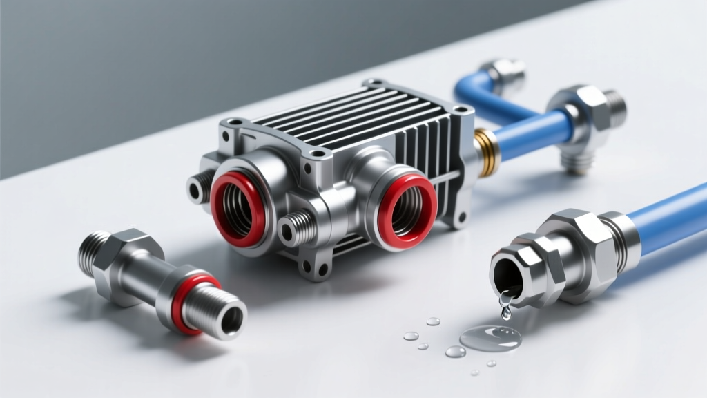
The vibration from the chassis and the hydraulic pulsation from the transmission pump will test every connection you made during your transmission cooler install. Most DIYers use either barb fittings with hose clamps or AN (Army-Navy) flare fittings.
AN Fitting Torque Specifications
If you opted for the superior route of braided lines and AN fittings, you must re-torque them after the first heat cycle. Aluminum expands and contracts significantly. Use an aluminum-jawed wrench to prevent marring the anodized finish, and adhere to these standard torque specs:
- -6 AN Fittings (3/8" hose): 10 to 12 ft-lbs.
- -8 AN Fittings (1/2" hose): 18 to 20 ft-lbs.
- -10 AN Fittings (5/8" hose): 25 to 30 ft-lbs.
Pro Tip: Never use Teflon tape on AN flare fittings or NPT-to-AN adapters that seal via O-ring. Teflon tape can shred and enter the transmission valve body, jamming shift valves and solenoids. Use liquid thread sealant rated for ATF, or rely on the O-ring seal.
Hose Clamp Degradation
If you used rubber hose and worm-gear clamps, inspect them every 15,000 miles. Rubber hoses compress and take a 'set' over time, causing worm-gear clamps to lose tension. Upgrade to constant-tension T-bolt clamps (like those from Mishimoto) which automatically adjust as the rubber expands and contracts with heat cycles.
Airflow & Fin Degradation: Stacked-Plate vs. Tube-and-Fin
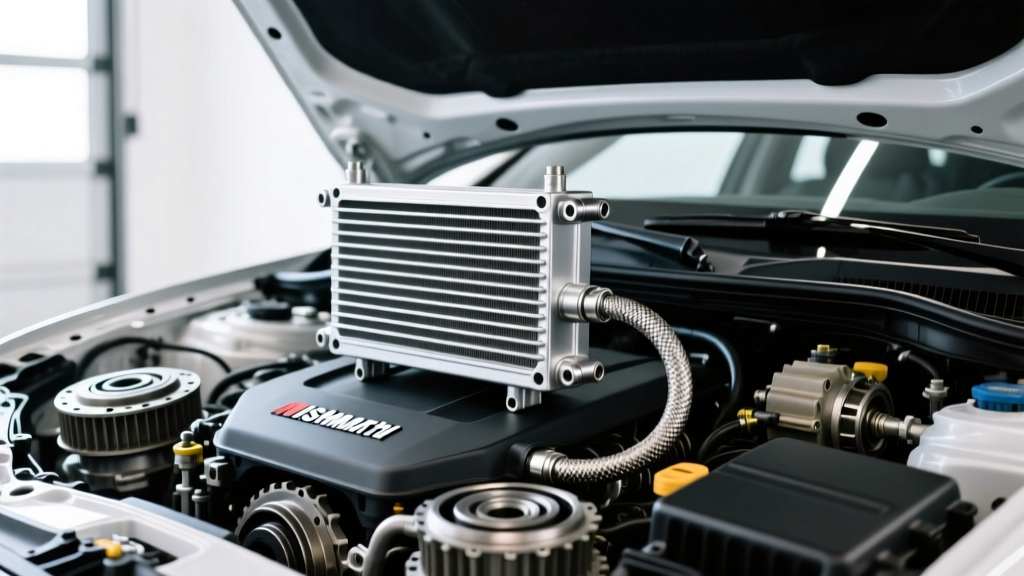
The physical core of your cooler is constantly bombarded by road debris, bugs, and salt. How you clean it depends entirely on the core design you chose during your transmission cooler install.
Tube-and-Fin Coolers
These are the most common and budget-friendly options (often in the $40-$80 range). They feature wide fin spacing, making them relatively easy to clean. You can safely use a soft-bristle brush and a garden hose to wash away bugs. Never use a high-pressure washer, as the fins are thin and will easily bend, blocking airflow and creating hot spots on the tubes.
Stacked-Plate Coolers
High-efficiency stacked-plate coolers (like the Derale Series 8000 or 9000) offer massive cooling capacity in a small footprint but feature incredibly tight fin spacing. Dirt and road grime will pack into these fins like concrete. To clean them, use a foaming coil cleaner (such as Nu-Calgon Evap Foam). Spray the foam onto the dry cooler core, let it sit for 10 minutes to lift the oils and dirt, and gently rinse with low-pressure water from the engine side outward to push debris back the way it came in.
The Thermal Breakdown Chart: Monitoring Fluid Health
The primary goal of your transmission cooler install is to keep fluid temperatures out of the danger zone. Heat is the number one enemy of ATF. The general rule of thumb is that for every 20°F increase in fluid temperature above 175°F, the lifespan of the fluid is cut in half.
| Operating Temp (°F) | Fluid Condition & Transmission Impact | Action Required |
|---|---|---|
| 175°F - 185°F | Optimal operating range for most modern ATFs (Dexron ULV, Mercon LV, ZF Lifeguard 8). | Normal maintenance. |
| 200°F - 210°F | Fluid oxidation accelerates. Additive packages begin to deplete. Fluid life halved. | Monitor closely; consider shorter drain intervals. |
| 220°F - 230°F | Varnish and sludge begin to form. Clutch material glazing occurs. | Immediate fluid change; inspect cooler for blockages. |
| 250°F+ | Seals harden and crack. Clutches slip. Total transmission failure is imminent. | Stop driving. Tow vehicle. Rebuild likely required. |
To monitor this, consider installing an inline digital temperature sender in the cooler return line (the line coming back from the cooler to the transmission). This gives you the most accurate reading of the fluid actually entering the pan and lubricating the valve body.
Line Upgrades: Ditching OEM Rubber for PTFE
Many beginners reuse the factory rubber transmission lines to save money during their install. OEM rubber is prone to dry rot, internal flaking, and swelling when exposed to the high detergency of modern synthetic ATFs. Furthermore, rubber lines expand under pressure, resulting in a 'spongy' feel and slightly delayed shift times.
The 2026 Standard: Upgrade to PTFE (Teflon) inner-core lines with a stainless steel braided exterior. PTFE lines do not expand under pressure, resist all chemical degradation, and can handle temperatures well over 400°F. While a 25-foot roll of PTFE line and reusable fittings will cost between $90 and $140 (compared to $30 for rubber), the reliability and shift-quality improvements make it a mandatory upgrade for any serious tow rig or performance build.
Flushing the Cooler Circuit: When and How
If your transmission experiences a catastrophic failure (e.g., a burnt clutch pack or a shattered torque converter), the cooler and lines will be packed with metallic debris and friction material. You cannot simply swap the transmission and reuse the cooler; the debris will immediately destroy the new unit.
The Flushing Procedure
- Disconnect: Remove the cooler lines from the transmission.
- Solvent: Use a dedicated, non-chlorinated transmission flushing solvent or mineral spirits. Do not use brake cleaner, as it can degrade the internal seals of certain cooler designs and leave a residue.
- Agitate & Push: Use compressed air (regulated to 40 PSI to avoid blowing out the cooler's internal brazing joints) to push the solvent through the cooler in the reverse direction of normal flow.
- Filter: Run the output through a white paper filter or a fine mesh screen to catch debris. Repeat until the solvent runs completely clear.
- Dry: Purge all solvent with dry compressed air before reconnecting to the new transmission.
Conclusion
A successful transmission cooler install is not a 'set it and forget it' modification. By dedicating 15 minutes every few oil changes to inspect your AN fittings, clean the cooler fins, and verify your thermal bypass operation, you ensure your transmission stays cool under pressure. Whether you are navigating steep mountain grades or sitting in stop-and-go traffic, proper cooler maintenance guarantees your drivetrain remains reliable, responsive, and ready for whatever the road throws at it.