The Drivetrain Hierarchy: Transfer Case vs. Differential
For beginners stepping into the world of four-wheel drive (4WD) and all-wheel drive (AWD) systems, the terminology can quickly become overwhelming. Two of the most critical, yet frequently confused, components in the drivetrain are the transfer case and the differential. While both are responsible for routing torque, they operate at entirely different stages of the power delivery process and serve distinct mechanical purposes.
To understand modern drivetrain diagnostics, you first need to understand the fundamental relationship between these two assemblies. The transfer case is the longitudinal split-point, while the differential is the lateral split-point.
| Component | Location | Primary Function | Typical Fluid Capacity |
|---|---|---|---|
| Transfer Case | Bolted to transmission output | Splits torque front-to-rear (longitudinal) | 1.5 to 2.5 Quarts |
| Front Differential | Front axle assembly | Splits torque left-to-right (lateral) | 1.2 to 2.0 Quarts |
| Rear Differential | Rear axle assembly | Splits torque left-to-right (lateral) | 1.5 to 2.5 Quarts |
In a traditional part-time 4WD system, like those found in older Jeep Wranglers or Chevrolet Silverados, the transfer case (such as the New Venture Gear NVG 241) uses a mechanical chain and a dog clutch to lock the front and rear driveshafts together. The differentials (often open or limited-slip) then allow the left and right wheels to rotate at different speeds during cornering. However, as we have moved into the 2026 automotive landscape, mechanical dog clutches have largely been replaced by sophisticated, computer-controlled wet clutch packs.
The Active Era: Blurring the Lines with Wet Clutch Packs
Modern AWD and torque-on-demand (TOD) 4WD systems blur the traditional lines between the transfer case and the differential. Systems like the BorgWarner 4406 or the GKN Twinster no longer rely on rigid mechanical lockups. Instead, they utilize multi-plate wet clutch packs submerged in specialized gear oil or automatic transmission fluid (ATF).
These wet clutch packs can be located inside the transfer case (to vary front/rear torque split) or inside the rear differential (for torque vectoring left/right). Because these clutches are 'wet'—meaning they operate entirely submerged in fluid to manage heat and friction—they require precise hydraulic pressure to engage smoothly without glazing or burning out. This is where advanced sensor technology becomes mandatory for drivetrain survival.
What is a Wet Differential Pressure Transducer?
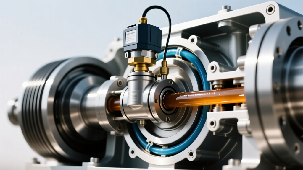
A wet differential pressure transducer is a specialized electromechanical sensor designed to measure hydraulic fluid pressure while completely submerged in, or directly exposed to, harsh lubricating environments like 75W-90 gear oil or specialized transfer case fluids.
In the context of the transfer case and differential relationship, this transducer is the critical feedback loop for the drivetrain control module (DTCM or PCM). When the vehicle's computer detects wheel slip, it commands a solenoid to apply hydraulic pressure to the wet clutch pack. The pressure transducer monitors the exact PSI or Bar of fluid pressing against the clutch pistons in real-time.
Why 'Wet' and 'Differential'?
- Wet Environment: Unlike standard manifold pressure sensors that measure air or dry gases, a wet transducer features a hermetically sealed diaphragm (often made of stainless steel or specialized ceramics) that prevents corrosive gear additives (like sulfur-phosphorus compounds found in GL-5 fluids) from destroying the internal piezoresistive elements.
- Differential Measurement: It measures the pressure differential between the clutch apply circuit and the sump (return) pressure. This ensures the computer knows the exact net force clamping the friction plates together, regardless of fluid temperature or viscosity changes.
According to engineering guidelines published by Bosch Mobility Solutions, modern wet pressure sensors must operate flawlessly across a temperature range of -40°C to 150°C, outputting a precise 0.5V to 4.5V analog signal or transmitting data via high-speed CAN bus to the drivetrain controller.
Diagnostic Guide: When the Transducer Fails
Because the wet differential pressure transducer lives inside the fluid bath, it is subject to extreme thermal cycling and microscopic metallic debris generated by the clutch packs and gears. When this sensor begins to fail, the relationship between the transfer case and the differential breaks down, resulting in distinct drivability issues.
Common Symptoms of Transducer Failure
- AWD/4WD Warning Lamp: The most immediate indicator. The PCM detects an irrational pressure reading and defaults the transfer case to a safe, open-differential state.
- Clutch Shudder on Takeoff: If the transducer reports lower pressure than actually exists, the computer overcompensates, causing the wet clutches to grab aggressively and shudder.
- Transfer Case Overheating: A failing sensor may cause the clutches to drag continuously, boiling the transfer case fluid and degrading the friction modifiers.
Relevant OBD2 Diagnostic Trouble Codes (DTCs)
When scanning the vehicle with an advanced bi-directional OBD2 scanner, look for the following manufacturer-specific or generic chassis/powertrain codes:
- C0569: System Voltage Malfunction (often related to the 5V reference circuit feeding the transducer).
- P2784: Input/Turbine Speed Sensor 'A'/'B' Correlation (The PCM sees clutch slip because the transducer isn't applying enough clamping pressure).
- U0136: Lost Communication With Differential Control Module (Common in active rear differentials like the Eaton eLSD).
Maintenance: Fluids, Torque Specs, and Service Intervals
The longevity of the wet differential pressure transducer is directly tied to the condition of the fluid it lives in. Degraded fluid, incorrect friction modifiers, or over-torqued drain plugs can destroy the sensor's diaphragm or cause internal fluid leaks.
Fluid Specifications and Capacities
Never use standard 80W-90 GL-5 gear oil in a transfer case or active differential equipped with wet clutch packs and pressure transducers unless explicitly specified. The sulfur additives can corrode the sensor's copper wiring harness pins, and the lack of friction modifiers will cause clutch chatter.
- GM AutoTrac II (P/N 88900333): Required for GM transfer cases with active wet clutches. Capacity: ~2.0 Quarts.
- Ford XL-12 (P-N 1L2Z-19590-AA): Used in Ford Torque-On-Demand transfer cases. Capacity: ~1.5 Quarts.
- Mopar ATF+4: Frequently used in BorgWarner transfer cases found in Jeep/Dodge applications. Capacity: ~1.9 Quarts.
Service Procedure and Torque Specifications
When performing a drain and fill on the transfer case or active differential to protect the transducer and clutch packs, adhere to strict mechanical procedures. The Society of Automotive Engineers (SAE) emphasizes that improper casing stress can misalign internal hydraulic galleries.
- Vehicle Leveling: Ensure the vehicle is perfectly level on a hoist or jack stands. An inclined vehicle will result in an under-filled transfer case, leaving the transducer and oil pump starved.
- Plug Removal: Always remove the fill plug first. If the drain plug is stripped, you still have a way to add fluid.
- Torque Specs: Most transfer case and differential fill/drain plugs utilize a 3/8-inch square drive. The aluminum or magnesium housings require a precise torque of 15 to 18 lb-ft. Over-torquing can crack the housing or distort the bore where the pressure transducer is seated.
- Fluid Level Check: Fluid should be exactly level with the bottom of the fill hole threads. For active differentials like the ZF Vectoring Drive, consult the ZF Group service documentation, as some require a specific temperature (e.g., 40°C) for an accurate level reading.
Summary: The Symbiotic Drivetrain
The relationship between the transfer case and the differential has evolved from a simple mechanical linkage into a highly coordinated, computer-managed symphony of hydraulics and gearing. The wet differential pressure transducer acts as the vital sensory organ in this system, ensuring that torque is distributed seamlessly, safely, and efficiently. By understanding how these components interact, and by adhering to strict fluid maintenance schedules, you can ensure your AWD or 4WD system remains reliable for hundreds of thousands of miles.