The Drivetrain Disconnect: Fluid Dynamics vs. Mechanical Friction
Automotive drivetrains require a mechanism to disconnect the engine from the transmission during gear changes and while at a stop. While manual vehicles rely on a mechanical friction clutch, automatic transmissions utilize a hydrodynamic fluid coupling. For enthusiasts, technicians, and engineering students navigating the 2026 automotive landscape, understanding exactly how a torque converter works in direct comparison to a traditional manual clutch reveals the brilliant engineering compromises that define modern vehicle performance. While electric vehicles utilize single-speed reductions and automated manual transmissions (DCTs) are prevalent in supercars, the hydrodynamic torque converter remains the undisputed king of heavy-duty towing, luxury NVH (Noise, Vibration, and Harshness) damping, and daily drivability.
The Hydrodynamic Marvel: How a Torque Converter Works
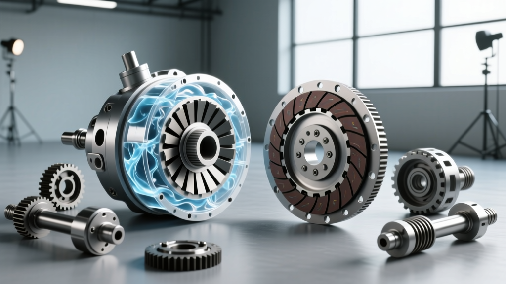
To grasp the comparison, we must first dissect the internal architecture of the torque converter. Unlike a solid mechanical link, a torque converter transfers power via automatic transmission fluid (ATF) shearing across three primary internal components: the impeller (pump), the turbine, and the stator.
- The Impeller: Bolted directly to the engine's flexplate, it spins at engine RPM, using centrifugal force to throw ATF outward and into the turbine.
- The Turbine: Connected to the transmission input shaft, it catches the fluid expelled by the impeller, translating hydraulic energy back into rotational mechanical energy.
- The Stator: Positioned between the impeller and turbine on a one-way clutch, the stator redirects returning fluid to enter the impeller in the direction of rotation. This redirection is the secret behind torque multiplication, allowing the converter to output more torque than the engine is physically producing at low RPMs.
In modern applications like the ZF 8HP 8-speed automatic, the torque converter also houses a Torque Converter Clutch (TCC) and a centrifugal pendulum absorber. According to engineering data from ZF Group's Automatic Transmission Division, these pendulum absorbers counteract torsional vibrations, allowing the TCC to lock up at incredibly low RPMs (sometimes as low as 1,000 RPM in 8th gear) without transferring engine drone into the cabin, thereby mimicking the 1:1 efficiency of a manual clutch.
Manual Friction Clutch Mechanics: The Solid Link
Conversely, a manual clutch assembly operates on the principles of dry (or sometimes wet) mechanical friction. The assembly consists of a heavy flywheel bolted to the engine, a friction disc splined to the transmission input shaft, and a pressure plate featuring a diaphragm spring.
When the clutch pedal is released, the diaphragm spring applies immense clamping force—often exceeding 2,800 lbs on OEM setups and up to 4,500+ lbs on aftermarket performance kits like a SPEC Stage 3+—sandwiching the friction disc against the flywheel. This creates a solid, 1:1 mechanical lock. There is no fluid shear, no stator, and zero torque multiplication. If a driver wants to launch a manual car hard, they must intentionally slip the clutch, generating massive amounts of localized heat and rapidly degrading the organic, Kevlar, or carbon friction material.
Engineering Comparison Matrix
The table below contrasts the operational characteristics of a modern heavy-duty automatic torque converter (specifically the GM 6L90E platform) against a high-performance manual friction clutch setup (Tremec T56 Magnum application).
| Parameter | GM 6L90E Torque Converter | Manual Friction Clutch (T56) |
|---|---|---|
| Coupling Medium | Dexron VI / Mercon LV ATF (Hydrodynamic) | Dry Friction Disc (Organic/Ceramic) |
| Torque Multiplication | Up to 2.4:1 (via Stator redirection) | 1:1 (Strictly Direct Drive) |
| Stall Speed (Slip) | 1,600 - 2,200 RPM (Stock) | Variable (Driver Controlled) |
| Parasitic Loss (Cruising) | Negligible (TCC Locked via PWM Solenoid) | Zero (Solid Mechanical Lock) |
| Heat Dissipation | Fluid routed to external transmission cooler | Radiated via flywheel/bellhousing (Prone to glazing) |
| NVH Damping | Internal damper springs / Pendulum absorbers | Clutch disc torsional springs (Limited capacity) |
Torque Multiplication vs. Direct Drive Gearing
One of the most profound differences in how a torque converter works compared to a clutch is torque multiplication. When a vehicle with a GM 6L80E or 6L90E transmission launches from a stop, the stator is locked by its one-way roller clutch. The fluid redirection multiplies engine torque by a factor of roughly 2.2:1 to 2.4:1 before it even reaches the transmission's planetary gearsets. If the engine produces 400 lb-ft at the flexplate, the transmission input shaft feels nearly 900 lb-ft.
A manual clutch cannot do this. To achieve similar off-the-line performance, a manual vehicle must rely on lower numerical transmission gearing (e.g., a steep 2.97:1 first gear) or a numerically higher rear differential ratio, which ultimately sacrifices top-end highway fuel economy. Aftermarket torque converters, such as a Circle D 3200-RPM stall unit, manipulate the impeller blade angle and stator design to shift the torque multiplication band higher into the RPM range, perfectly matching aggressive camshaft profiles.
Thermal Management and Parasitic Drag
Before the advent of electronic Pulse Width Modulation (PWM) solenoids, torque converters suffered from constant fluid slip, resulting in parasitic power loss and immense heat generation. This necessitated robust external cooling systems, such as Hayden Automotive stacked-plate coolers, to prevent ATF degradation. Today, the TCC acts essentially as an automated internal clutch. Once the vehicle reaches cruising speed, the TCC solenoid applies a friction lining (often a woven carbon or Kevlar composite) that mechanically locks the turbine to the impeller, eliminating slip and matching the 100% mechanical efficiency of a manual clutch.
"The evolution of the TCC apply strategy is what saved the automatic transmission. By utilizing controlled slip during gear changes and full lockup during cruising, modern automatics achieve thermal efficiency that rivals, and sometimes beats, manual drivetrains in real-world highway testing." — Technical bulletins from Sonnax Transmission Company.
Diagnosing Failure: Shudder vs. Slip
Because the friction interfaces in both systems are subject to wear, they exhibit distinct failure symptoms that technicians must accurately diagnose.
Torque Converter Shudder and TCC Failure
When the TCC friction lining degrades, or when the ATF loses its specific friction-modifying additives, the converter fails to lock up smoothly. This results in torque converter shudder—a rhythmic, low-frequency vibration typically felt between 40-60 mph under light throttle application. The TCC is rapidly applying and releasing (micro-slipping) because the degraded fluid cannot maintain a stable hydraulic boundary.
Diagnostic Action: Technicians often first attempt a fluid exchange using OEM-specified fluids (like ACDelco Dexron VI) paired with a specialized friction modifier additive (e.g., Lubegard Dr. Tranny Shudder Fixx). If the shudder persists, the friction material has physically delaminated, requiring transmission removal, torque converter replacement (often upgrading to a billet-aluminum cover to prevent flexplate warping), and a complete valve body inspection to ensure the TCC apply valve hasn't scored the valve body bore.
Manual Clutch Slip and Glazing
A manual clutch fails via slip, characterized by a rapid rise in engine RPM without a proportional increase in vehicle speed, usually under heavy load or in higher gears. This is caused by the friction disc glazing (overheating and turning to glass) or the pressure plate diaphragm fingers losing their spring tension due to heat cycling.
Diagnostic Action: Unlike a torque converter, a slipping manual clutch cannot be fixed with a fluid change. It requires a physical teardown: dropping the transmission, resurfacing or replacing the dual-mass flywheel (which can cost upwards of $1,200 for OEM parts), and installing a new clutch kit (such as a Luk RepSet or Sachs OE replacement). Furthermore, a leaking engine rear main seal or transmission input shaft seal can contaminate the dry clutch disc with oil, causing catastrophic slip that mimics a worn-out friction pad.
Conclusion: The Right Tool for the Drivetrain
Understanding how a torque converter works in contrast to a manual clutch highlights why each system dominates its respective niche. The manual friction clutch offers unparalleled driver engagement, zero parasitic fluid loss, and a lightweight, simple mechanical package ideal for track use and lightweight sports cars. However, it demands driver intervention and lacks torque multiplication.
The modern torque converter, armed with advanced stator geometries, multi-stage TCC lockup strategies, and integrated pendulum dampers, provides seamless torque multiplication, superior heavy-load launch capabilities, and luxury-grade NVH isolation. As research published via SAE International Technical Papers continues to demonstrate, the hydrodynamic torque converter's ability to multiply torque while simultaneously isolating torsional engine vibrations ensures its continued relevance in internal combustion and hybrid powertrains well into the future.