Introduction: Hydrodynamics vs. Mechanical Friction
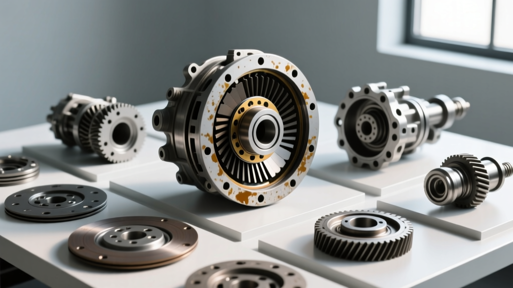
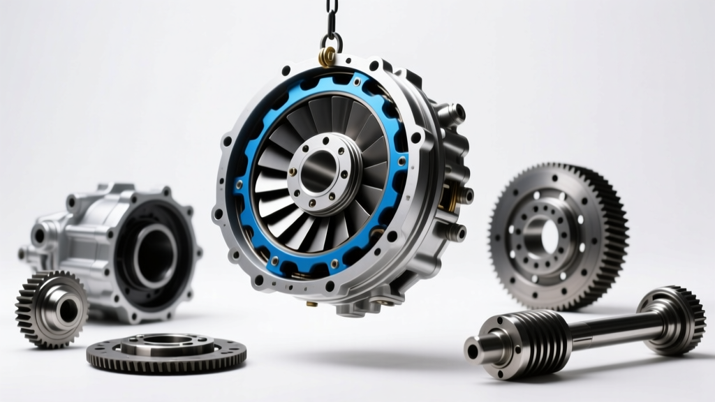
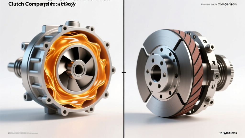
When students or enthusiasts first search for a picture of torque converter anatomy, they are typically met with simplified cutaway diagrams showing an impeller, turbine, and stator. However, understanding how this hydrodynamic device compares to a traditional mechanical friction clutch—found in manual transmissions and Dual-Clutch Transmissions (DCTs)—requires looking far beyond basic illustrations. While both components serve the primary function of coupling the engine's crankshaft to the transmission input shaft, their methods of torque transfer, thermal management, and failure modes are fundamentally opposed.
In this technical deep-dive, we will dissect the engineering paradigms separating fluid couplings from dry and wet friction clutches, utilizing real-world data from platforms like the GM 6L80, the ZF 8HP, and the Tremec TR-6060.
The Physics of Torque Transfer
Hydrodynamic Multiplication
A torque converter operates on the principles of hydrodynamic fluid coupling. The engine drives the impeller, which accelerates Automatic Transmission Fluid (ATF) outward via centrifugal force. This high-velocity fluid strikes the turbine, transferring kinetic energy. The stator, mounted on a one-way clutch, redirects returning fluid to multiply torque during the "stall" or "multiplication" phase. Modern converters typically achieve a torque multiplication ratio between 2.0:1 and 2.5:1. This allows a vehicle with a 3.0L diesel engine producing 400 lb-ft of crank torque to apply upwards of 900 lb-ft to the transmission input shaft during heavy launch, without any mechanical friction material wear.
Mechanical Friction Coupling
Conversely, a manual or DCT friction clutch relies on the coefficient of friction (μ) between clamped surfaces. A flywheel, friction disc, and pressure plate create a direct mechanical lock. The torque capacity is dictated by the clamp load of the diaphragm spring and the friction material (organic, Kevlar, or sintered iron). Unlike the torque converter, a friction clutch offers a strict 1:1 torque ratio. It cannot multiply torque; it can only transmit what the engine produces, making launch modulation entirely dependent on the driver's or mechatronic unit's ability to manage slip and thermal loading.
The Torque Converter Clutch (TCC): Bridging the Paradigm
To eliminate the parasitic slip inherent in fluid couplings at cruising speeds, modern automatics utilize a Torque Converter Clutch (TCC). When you examine a detailed picture of torque converter lockup mechanisms, you will see a multi-plate or single-plate friction clutch housed *inside* the converter itself.
In advanced units like the ZF 8HP 8-speed automatic, the TCC features a centrifugal pendulum absorber (CPA). This integrated damper cancels out engine torsional vibrations, allowing the TCC to lock up as early as 1,000 RPM in 8th gear, effectively turning the hydrodynamic converter into a rigid mechanical clutch to maximize fuel economy without inducing NVH (Noise, Vibration, and Harshness) into the chassis.
Technical Specification & Performance Matrix
The following matrix contrasts the operational parameters of a heavy-duty automatic torque converter against a high-performance manual friction clutch.
| Parameter | GM 6L80 Torque Converter | ZF 8HP Torque Converter (w/ CPA) | Tremec TR-6060 Friction Clutch |
|---|---|---|---|
| Coupling Type | Hydrodynamic + TCC Lockup | Hydrodynamic + Multi-plate TCC | Dry Mechanical Friction |
| Torque Multiplication | ~2.2:1 (Stall Phase) | ~1.9:1 (Stall Phase) | 1:1 (Direct Mechanical) |
| Peak Torque Capacity | ~650 lb-ft (TCC Applied) | ~738 lb-ft (TCC Applied) | ~800 lb-ft (Sintered Iron) |
| Thermal Dissipation | External Cooler (1.5 - 2.0 GPM) | External Cooler / Block Integration | Ambient Air / Bellhousing |
| Fluid Medium | Dexron VI (5.8 cSt @ 100°C) | ZF LifeguardFluid 8 | None (Dry) |
| Parasitic Loss (Unlocked) | 3% - 8% (Slip dependent) | 2% - 6% (Slip dependent) | 0% (Fully Locked) |
Thermal Dynamics and Parasitic Loss
Heat is the primary enemy of both systems, but it manifests differently. In a torque converter, power loss during the slip phase is converted directly into heat within the ATF. The formula for thermal generation is P_loss = Torque × Δω (difference in angular velocity between impeller and turbine). During a 5-second stall test at 2,500 RPM, a converter can generate over 30,000 BTUs of heat. This necessitates robust external cooling circuits; a restricted 6L80 cooler line will rapidly degrade the ATF's friction modifiers, leading to TCC failure.
Friction clutches manage heat through mass and surface area. A heavy cast-iron flywheel acts as a heat sink. However, repeated slip without adequate airflow leads to "glazing," where the organic resin binders melt and crystallize, permanently dropping the coefficient of friction and causing severe clutch chatter.
Divergent Failure Modes and Symptom Diagnostics
Because the coupling mechanisms differ, their failure symptoms require entirely different diagnostic approaches. As detailed in Sonnax technical bulletins, hydraulic and mechanical faults often mimic one another but stem from different root causes.
Torque Converter Specific Symptoms
- TCC Shudder: A rhythmic vibration (typically 30-50 Hz) felt between 40-60 mph under light throttle. This is caused by the TCC friction material losing its static-to-kinetic friction stability, resulting in micro-slip oscillations. Often misdiagnosed as an engine misfire or driveshaft imbalance.
- Stator Clutch Failure: If the stator's internal one-way roller clutch fails and freewheels in both directions, the converter loses torque multiplication. The symptom is a severely sluggish takeoff from a stop, requiring excessive throttle to move the vehicle, while highway cruising remains relatively unaffected.
- Fin Deflection / Ballooning: Under high-line pressure or extreme torque, the converter cover can physically balloon outward. This pushes the converter into the transmission pump, destroying the pump bushing and causing front seal leaks.
Friction Clutch Specific Symptoms
- Clutch Chatter: Violent shaking upon engagement. Usually caused by hot-spots on the flywheel, oil contamination on the friction disc, or broken torsional damper springs inside the disc hub.
- Throw-Out Bearing (TOB) Failure: A high-pitched whine or grinding that changes pitch with engine RPM and clutch pedal position. Unlike TC issues, this is strictly mechanical and isolated to the bellhousing.
- Pressure Plate Fatigue: Over time, the diaphragm spring loses its temper and clamping force. The symptom is high-RPM slip in top gears, even when the pedal is fully released.
Rebuild Economics and Assembly Torque Specifications
When failure occurs, the repair economics diverge sharply. A friction clutch replacement requires dropping the transmission or engine, replacing the disc, pressure plate, and resurfacing the flywheel. A heavy-duty clutch kit (e.g., South Bend or McLeod) ranges from $450 to $900, with labor averaging 6-9 hours.
Torque converters are rarely rebuilt in standard repair shops due to the requirement of a lathe to cut the converter lid, balance the assembly, and weld it back together. Remanufactured units from suppliers like Precision Industries or Sonnax-equipped rebuilders cost between $600 and $1,200. OEM replacements easily exceed $1,500.
Critical Assembly Specs
When installing a torque converter, verifying clearance and torque specs is vital to prevent immediate pump destruction. For the GM 6L80 and 10L80 platforms:
- TC-to-Flexplate Bolt Torque: 35 lb-ft (47 Nm). Never use impact guns, as this can distort the flexplate and induce harmonic vibrations.
- TC Pull-Away (Clearance): Must measure between 0.125" and 0.375" (3.1mm - 9.5mm) from the flexplate pad to the converter stud. Zero clearance will preload the transmission pump gear, causing catastrophic failure within the first 50 miles.
- Flush Requirement: Because a failing TCC sheds friction material into the fluid, the transmission cooler and lines MUST be flushed using a minimum of 2.5 gallons of fresh ATF to prevent debris from jamming the new converter's lockup valves.
Conclusion
While a simple picture of torque converter components might suggest a rudimentary fluid pump, the reality is a highly engineered hydrodynamic device capable of torque multiplication and seamless lockup. Friction clutches offer unmatched mechanical efficiency and direct driver feedback, making them ideal for track and heavy-towing applications. However, the modern torque converter's ability to multiply torque, absorb torsional vibrations via CPA dampers, and manage immense thermal loads ensures its continued dominance in daily-driven and heavy-duty automatic platforms.