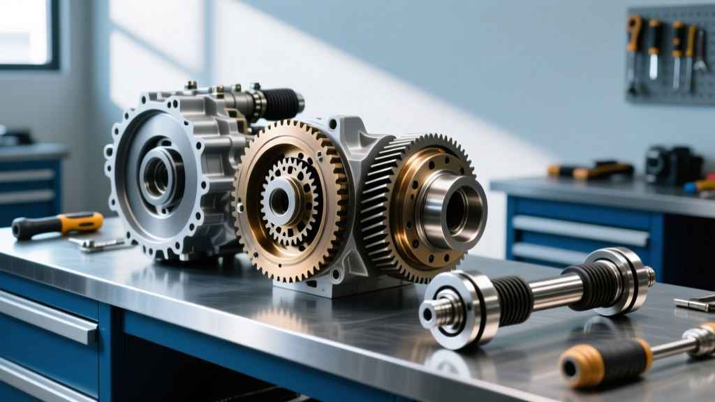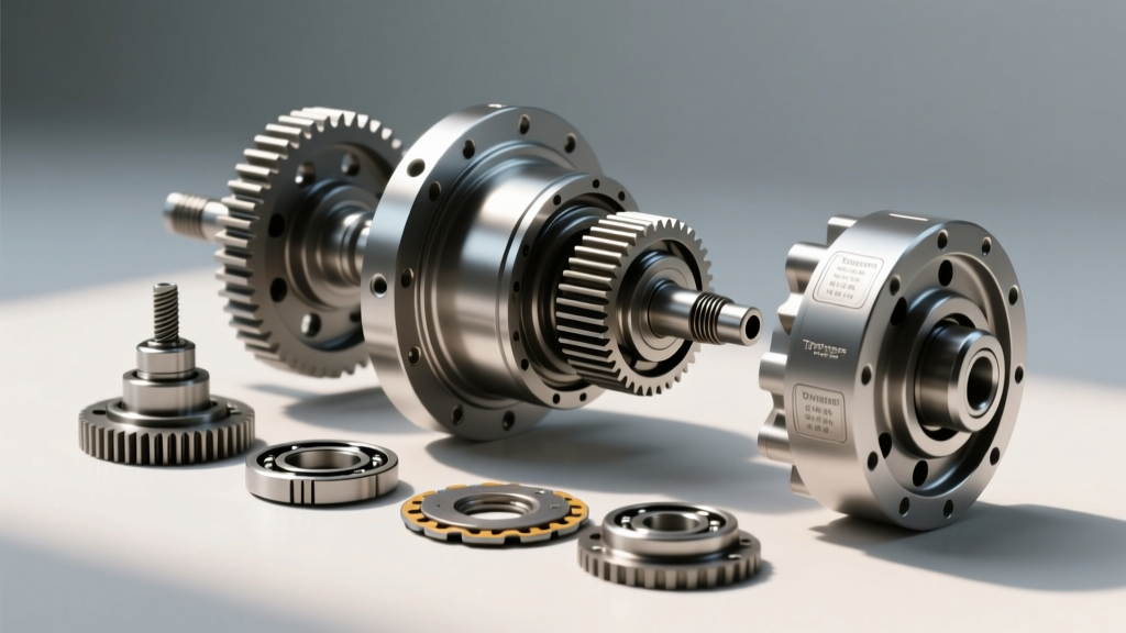
The High-Stress Drivetrain: Why Component ID Matters
Achieving reliable Texas drivetrain performance requires more than just bolting on aftermarket parts; it demands a forensic understanding of component identification and failure modes. Whether you are towing a 12,000-lb gooseneck trailer across I-10 in July heat or crawling through the Hill Country, the driveline is subjected to immense torsional stress and thermal degradation. Misdiagnosing a driveline vibration or clunk often leads to unnecessary parts swapping. In this 2026 diagnostic guide, we break down exact component identification, measurement protocols, and symptom-to-solution matrices for modern heavy-duty and performance 4WD platforms.
Mapping the Power Flow: From Transmission Output to Hub
Before diagnosing a fault, you must accurately map the power flow. In a typical front-engine, longitudinal 4WD layout (such as a GM 6L80E or Ford 10R80 paired with a transfer case), the drivetrain sequence is:
- Transmission Output Shaft & Tailhousing Seal
- Slip Yoke or Fixed Flange (Connecting to the transfer case or directly to the driveshaft)
- Driveshaft Tubing (Aluminum, steel, or carbon fiber)
- Universal Joints (U-Joints) or CV Joints
- Differential Pinion Flange & Yoke
- Ring and Pinion Gear Set
- Differential Carrier & Axle Shafts
- Outer CV Joints (IFS setups) or Spindle Bearings (Solid Axles)
Visual & Auditory Symptom Matrix
Drivetrain symptoms are highly dependent on vehicle speed, load, and throttle position. Use this matrix to isolate the failing component before putting a wrench to the truck.
| Symptom | Condition / Trigger | Primary Suspect Component | Verification Method |
|---|---|---|---|
| High-frequency shudder (45-55 mph) | Light throttle, torque converter lockup | Driveshaft out of phase / Worn slip yoke | Check U-joint phasing marks; measure slip yoke play (max 0.005" radial) |
| Metallic clunk on engagement | Shifting from Park to Drive/Reverse | Differential backlash / Worn axle splines | Measure ring gear backlash (spec: 0.006"-0.010") |
| Howling / Whining | Coast vs. Drive (changes with load) | Pinion bearing preload / Gear wear | Coast = Pinion bearing; Drive = Ring/Pinion contact pattern |
| Cyclic clicking on turns | Low speed, sharp steering angle | Outer CV Joint (Rzeppa) | Inspect boot for grease sling; bind joint by hand |
| Roaring that mimics tire noise | Speed-proportional, changes on swerves | Hub assembly / Carrier bearing | Load/unload bearings via swerving; use chassis ear |
Deep Dive: Identifying Failing Components Under Load
To maintain peak Texas drivetrain performance, you must replace failing parts with exact-match or upgraded equivalents. Here is how to identify the most common failure points.
1. Universal Joints: Spicer 1350 vs. 1410 vs. 1480
Universal joints are the most abused components in any lifted or heavily towed truck. Identifying the correct series is critical for ordering replacements. Do not rely on visual guesses; use digital calipers.
- Spicer 1350 Series: Cap diameter is exactly 1.188 inches. Cross width (outside of cap to outside of cap) is 3.625 inches. Common on 1/2-ton and 3/4-ton trucks (e.g., GM 2500HD, Ford F-250).
- Spicer 1410 Series: Cap diameter remains 1.188 inches, but the cross width increases to 4.188 inches. Often found in 1-ton applications or as an aftermarket upgrade.
- Spicer 1480 Series: Cap diameter jumps to 1.312 inches with a 4.188-inch width. Standard on heavy-duty commercial chassis and high-horsepower off-road builds.
Failure Mode: Look for 'rust dust' around the caps, indicating brinelling and lack of lubrication. According to Dana Engineering, non-greaseable joints often outlast greaseable ones in high-stress environments because the solid cap design resists deformation under extreme torsional loads.
2. CV Axles and Spline Counting (IFS Setups)
Independent Front Suspension (IFS) trucks rely on CV axles to transfer power while steering and articulating. When an axle breaks on the trail, identifying the spline count is mandatory for sourcing a replacement.
- GM 6-Lug (1500 Series): Typically utilizes a 33-spline outer stub shaft.
- Ford Super Duty (Dana 60 IFS / Solid Axle): Uses a robust 35-spline configuration.
- RAM 2500 (AAM 9.25 IFS): Features a 33-spline inner and a specific 34-spline outer hub interface.
Diagnostic Tip: If you experience a vibration that disappears when the front hubs are unlocked (in 2WD), the fault lies in the front driveshaft, differential, or inner CV tripod joints, not the outer Rzeppa joints.
3. Differential Pinion Bearings and Crush Sleeves
A whining differential is a hallmark of incorrect pinion bearing preload. Modern differentials use a crush sleeve to set this preload. When replacing a pinion seal, many technicians mistakenly reuse the crush sleeve or over-torque the pinion nut. The pinion nut torque on a GM 9.5-inch 14-bolt axle can exceed 250 lb-ft to crush the sleeve to the exact rotational torque spec (typically 15-25 in-lbs of drag). Always use a new crush sleeve and a beam-style torque wrench to measure rotational drag.
Precision Assembly: Torque Specifications & Clearances
Drivetrain longevity relies on exact torque values. Below are baseline specifications for common heavy-duty platforms. Always verify with your specific OEM service manual, as variations exist between model years.
| Component | Application | Torque Specification | Notes |
|---|---|---|---|
| U-Joint Strap Bolts | Spicer 1350 / 1410 | 18 - 25 lb-ft | Use Grade 8 hardware; apply medium Loctite |
| Driveshaft Center Support Bearing | GM / Ford 2-Piece Shaft | 35 - 45 lb-ft | Ensure rubber isolator is not bound |
| Front Axle Hub Nut | GM 1500 (6L80E / 8L90) | 155 - 180 lb-ft | Torque in 3 stages; stake nut if applicable |
| Differential Cover Bolts | Dana 60 / AAM 11.5 | 25 - 30 lb-ft | Cross-pattern tightening; use RTV or gasket |
| Ring Gear Bolts | Standard 10/12 Bolt | 75 - 90 lb-ft | Apply red Loctite; left-hand threads on some models |
Advanced Diagnostic Tools for the Modern Driveline
In 2026, guessing is no longer acceptable. Professional drivetrain diagnosis requires specialized equipment:
- Wireless Chassis Ear: Clamped to the differential housing, transfer case, and transmission tailhousing, this tool allows you to isolate bearing whines from gear noise while driving at highway speeds.
- Thermal Imaging Camera: After a 20-mile test drive under load, scan the U-joints and pinion yoke. A failing U-joint or dry carrier bearing will show a thermal signature 30°F to 50°F hotter than surrounding components due to friction.
- Laser Tachometer / Driveline Angle Finder: Vibrations often stem from improper operating angles. The working angle of the transmission output shaft and the differential pinion must be equal and opposite (typically 1° to 3° max). Use a digital angle finder on the driveshaft tubing and yokes to verify geometry, especially on lifted trucks where aftermarket control arms may be required to correct pinion angles.
2026 Sourcing and Replacement Costs
Understanding the financial scope of a drivetrain repair helps in deciding between OEM replacement, aftermarket upgrades, or complete platform swaps. Based on current market data and RockAuto pricing trends for early 2026:
- Heavy-Duty CV Axle Assembly (OEM Equivalent): $180 - $350 per side. (Upgraded chromoly off-road shafts run $600 - $900+).
- Spicer 1350 U-Joint Kit: $25 - $45. (Labor to swap on-vehicle: 1.5 hours @ $150/hr).
- Ring and Pinion Master Overhaul Kit: $350 - $550 (Includes Timken bearings, shims, crush sleeve, seals). Professional setup labor typically ranges from $400 to $600 per axle.
- Carbon Fiber Driveshaft Upgrade: $1,200 - $1,800. Justified for high-horsepower builds seeking to reduce rotational mass and eliminate high-speed harmonic vibrations.
Mastering Texas drivetrain performance is an exercise in precision. By accurately identifying components via physical measurement, understanding the physics of torsional stress, and adhering strictly to torque and clearance specifications, you can build a driveline that survives both the highway and the harshest off-road environments. For further reading on driveline geometry standards, refer to the SAE International technical papers on universal joint operating angles and vibration damping.