The Misconception: Torque Converter Stall Test vs. TCC Diagnostics
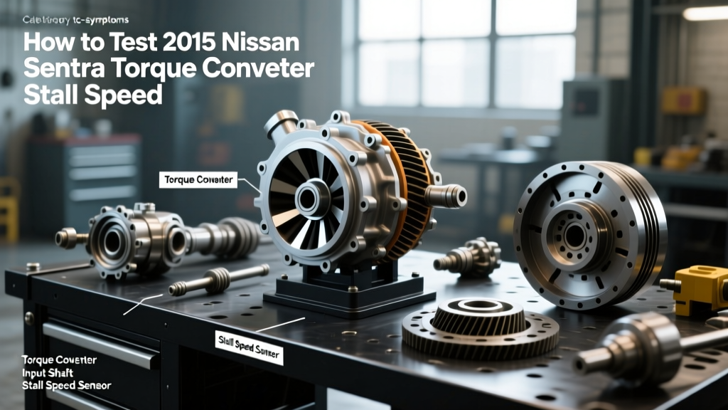
When an automatic transmission exhibits shudder, harsh shifting, or triggers a Check Engine Light with codes like P0740 (Torque Converter Clutch Circuit Malfunction) or P0742 (TCC Stuck On), many DIY mechanics and junior technicians immediately reach for the brake pedal and throttle to perform a torque converter stall test. This is a fundamental diagnostic error. While a stall test is an excellent method for evaluating the health of the torque converter's stator one-way clutch and measuring maximum engine torque output, it is virtually useless—and potentially dangerous—when diagnosing torque converter clutch (TCC) solenoid problems.
As of 2026, the vast majority of automatic transmissions on the road, from the GM 6L80 to the ZF 8HP and Ford 10R80, utilize Pulse Width Modulated (PWM) TCC solenoids. These solenoids do not simply turn 'on' and 'off'; they modulate hydraulic pressure hundreds of times per second to create a controlled, micro-slip lockup phase. A stall test cannot measure PWM duty cycles, electrical resistance, or hydraulic bore wear. In this expert guide, we will break down exactly why the stall test is the wrong tool for TCC diagnostics and outline the proper, data-driven workflow for isolating solenoid failures.
Why Stall Testing is Dangerous with TCC Codes
Consider a scenario where a vehicle has a P0742 code, meaning the TCC is mechanically or hydraulically stuck in the 'applied' (locked) position. If you attempt a torque converter stall test under these conditions, the engine will immediately bog down and stall the moment you shift into Drive or Reverse and apply the brakes. Because the lockup clutch is physically engaged, the engine is directly coupled to the drivetrain. Forcing the engine against the brakes in this state sends massive shock loads through the flexplate, CV axles, and transmission mounts. You are not testing the converter; you are stress-testing the driveline hardware.
Expert Diagnostic Workflow for TCC Solenoid Problems
To accurately diagnose a faulty TCC solenoid, you must move away from archaic mechanical tests and embrace bi-directional scanning and electrical bench testing. According to the diagnostic protocols outlined by the Automatic Transmission Rebuilders Association (ATRA), a proper TCC diagnosis requires a three-phase approach.
Phase 1: Bi-Directional Scanning and Slip Speed Analysis
Connect an advanced bi-directional scan tool and monitor the 'TCC Slip Speed' PID (Parameter Identification) while driving at a steady highway speed (typically 45-60 mph in top gear).
- Normal Operation: When the PCM commands TCC apply, the slip speed should smoothly drop from roughly 100-150 RPM down to less than 20 RPM (or 0 RPM on non-PWM systems).
- Solenoid Electrical Failure: If the slip speed remains high (e.g., 150+ RPM) despite a 100% commanded duty cycle, the solenoid is either electrically dead, mechanically stuck closed, or the hydraulic circuit is leaking.
- Stuck On (P0742): If slip speed reads 0 RPM before the PCM commands lockup, the solenoid valve is jammed open, or the TCC regulator valve in the valve body is seized.
Phase 2: Electrical Bench Testing (Resistance & PWM)
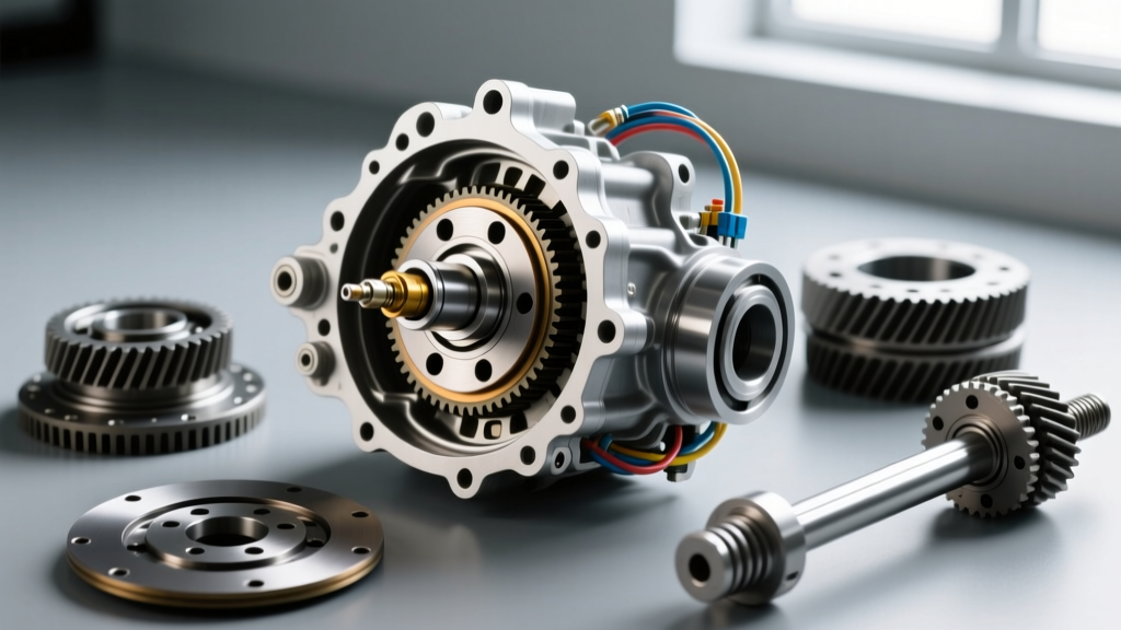
If the scan tool data points to an electrical fault, drop the transmission pan and test the solenoid directly. You must use a high-quality digital multimeter to measure resistance across the solenoid pins. Note that resistance values are highly temperature-dependent. Always compare your readings to the manufacturer's specifications at the current ambient or fluid temperature (usually standardized at 68°F / 20°C).
Expert Tip: Never use a standard 12V test light or apply direct 12V battery power to a modern PWM TCC solenoid. These solenoids are designed for low-current, high-frequency (typically 32Hz to 1000Hz) PWM signals. Applying raw 12V DC will instantly fry the internal coil windings.
TCC Solenoid Specifications by Transmission Model
Below is a reference table for common transmission models, detailing the specific OEM part numbers and expected resistance ranges for their respective TCC solenoids. Always verify with your specific year's service manual, as mid-year running changes can alter part numbers.
| Transmission Model | OEM TCC Solenoid Part # | Resistance (Ohms @ 68°F) | Solenoid Type |
|---|---|---|---|
| GM 4L60E / 4L65E | AC Delco 24227747 | 10.0 - 15.0 Ω | PWM (32Hz) |
| GM 6L80 / 6L90 | AC Delco 24252114 (TEHCM) | 10.0 - 14.0 Ω | PWM Variable Force |
| Ford 6R80 / 6R140 | 9L7Z-7G101-A | 1.5 - 2.5 Ω | Low-Resistance PWM |
| ZF 8HP (Chrysler/BMW) | ZF 0501 216 243 (Mechatronic) | 5.0 - 7.0 Ω | EDS (Electro-Pressure) |
Mechanical Realities: When the Solenoid is Fine but the TCC Fails
One of the most common pitfalls in TCC diagnosis is replacing a perfectly good electrical solenoid, only to find the shudder or slip condition persists. As detailed in the technical resources at Sonnax, the root cause of many perceived 'solenoid failures' is actually hydraulic cross-leaking within the valve body.
Valve Body Bore Wear and TCC Regulator Valves
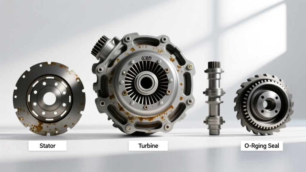
The TCC solenoid feeds hydraulic fluid to a TCC regulator valve or TCC control valve located in the valve body. Over time, the constant oscillation of this aluminum valve inside its cast-aluminum or steel bore causes severe wear. When the bore becomes ovalized, pressurized apply fluid bypasses the valve and exhausts to the sump. The PCM sees the resulting TCC slip, assumes the solenoid is failing, and maxes out the PWM duty cycle to compensate. Eventually, the PCM sets a code for low TCC pressure. If you do not inspect the valve body bore for wear or install a sleeve repair kit (such as a Sonnax Zip Valve kit), replacing the solenoid will not fix the issue.
Fluid Degradation and Friction Modifier Depletion
Before condemning the solenoid or the valve body, evaluate the transmission fluid. Modern TCC apply strategies rely heavily on the specific friction modifiers present in fluids like Dexron VI, Mercon LV, or ZF Lifeguard 8. If the fluid has been subjected to extreme thermal breakdown, or if an incorrect universal ATF was used, the lockup clutch lining will grab and release erratically, causing a violent shudder between 35-50 mph. This mechanical shudder is often misdiagnosed as a failing PWM solenoid because the scan tool will show erratic slip speed RPMs. Always perform a fluid exchange with the exact OEM-specified fluid and add a tube of a high-quality shudder fix additive (like Lubegard Instant Shudder Fixx) as a diagnostic test before tearing into the valve body.
Replacement Best Practices, Torque Specs, and 2026 Costs
If your electrical and hydraulic diagnostics confirm a failed TCC solenoid, proper installation is critical. Modern transmissions are highly sensitive to debris. A single metal shaving from a worn clutch pack can lodge in the new solenoid's pintle, causing an immediate P0740 code upon reassembly.
Crucial Installation Steps
- Cleanliness: Use compressed air and lint-free shop towels to clean the solenoid mating surfaces in the valve body or TEHCM (Transmission Electro-Hydraulic Control Module).
- O-Ring Lubrication: Always lubricate the new solenoid's rubber O-rings with the specific ATF being used. Never use petroleum jelly or assembly lube, which can contaminate the friction materials.
- Torque Specifications: Valve body and TEHCM bolts are notoriously easy to strip or snap. Use a calibrated inch-pound torque wrench. For example, GM 6L80 TEHCM-to-case bolts require exactly 8 Nm (71 lb-in). ZF 8HP Mechatronic sleeve bolts typically require 10 Nm (89 lb-in). GM 4L60E valve body-to-spacer plate bolts are torqued to 97 lb-in (11 Nm).
Estimated Repair Costs (2026 Market Rates)
Repair costs vary wildly depending on whether the solenoid is externally mounted on the valve body or integrated into a sealed mechatronic unit. Below is a realistic breakdown based on current independent shop labor rates ($130-$160 per hour):
- GM 4L60E / Ford 6R80 (Pan Drop, Solenoid R&R): $350 - $550 total. (Includes 2-3 hours labor, $50-$120 part, and fluid/filter).
- GM 6L80 / 8L90 (TEHCM Replacement): $900 - $1,400 total. The TCC solenoid is not serviced separately; the entire TEHCM must be replaced and programmed via J2534 pass-through.
- ZF 8HP / Chrysler 8-Speed (Mechatronic Unit): $1,800 - $2,800+ total. Requires mechatronic unit replacement, ZF Lifeguard 8 fluid, and proprietary security gateway programming.
- Valve Body Bore Repair (If required): Add $250 - $450 for a re-manufactured valve body or Sonnax sleeve kit installation and hydraulic testing.
Final Thoughts on Modern Drivetrain Diagnostics
The days of diagnosing automatic transmissions with a pressure gauge and a torque converter stall test are long gone. Today's torque converter clutch systems are marvels of electro-hydraulic engineering, requiring a technician to think like an electrical engineer and a hydraulic specialist simultaneously. By relying on bi-directional slip speed analysis, precise ohm-meter testing, and a thorough understanding of valve body hydraulics, you can accurately pinpoint TCC solenoid problems on the first attempt, saving time, money, and unnecessary parts swapping.