The Physics of Power Transfer: Friction vs. Hydrodynamics
When evaluating drivetrain efficiency and power delivery, the torque converter vs clutch comparison remains one of the most fundamental debates in automotive engineering. While both systems serve the primary function of coupling and decoupling the engine's rotational mass from the transmission's input shaft, their methods of power transfer are vastly different. Understanding these differences is not just academic; it directly dictates how the engine's rotating assembly is physically mounted, which brings us to the critical importance of flywheel to torque converter bolts torque specs in modern automatic transmissions.
A traditional manual friction clutch relies on raw mechanical clamping force. A diaphragm or coil-spring pressure plate squeezes a friction disc (faced with organic, ceramic, or Kevlar compounds) against a heavy cast-iron or billet steel flywheel. The transfer of torque is purely mechanical, governed by the coefficient of friction and the clamping load (often exceeding 2,500 lbs of pressure in performance applications). Slippage generates immense heat and is only tolerated during the engagement phase.
Conversely, a torque converter operates on hydrodynamic principles. The impeller (driven by the engine) accelerates transmission fluid outward via centrifugal force, which then strikes the turbine (connected to the transmission input shaft). A stator redirects the fluid to multiply torque—often achieving a 2.0:1 to 2.5:1 multiplication ratio at stall. This fluid coupling allows the vehicle to stop while the engine runs, and it absorbs torsional vibrations that would otherwise shatter gear teeth or rattle the chassis.
The Bridge Between Worlds: The Torque Converter Clutch (TCC)
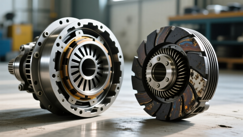
The line between a hydrodynamic coupling and a mechanical clutch blurs significantly when we examine the Torque Converter Clutch (TCC). To eliminate the inherent parasitic slip of fluid coupling at highway speeds, modern automatics employ a TCC lockup mechanism. When engaged by the transmission control module (TCM), a hydraulic piston applies a woven carbon or cellulose friction liner directly against the inner machined surface of the torque converter cover.
Expert Insight: When the TCC locks, the torque converter effectively becomes a mechanical clutch. The entire rotational mass of the engine is now rigidly coupled to the transmission input shaft. At this exact moment, the physical mounting hardware—specifically the flexplate and the fasteners securing it to the converter—bears the full brunt of engine torsional harmonics and combustion pulses.
In a manual transmission, the heavy flywheel acts as a rotational mass damper, smoothing out the firing impulses of the engine. In an automatic, the torque converter's internal damper springs (or a dual-mass flexplate) must absorb these harmonics when the TCC is locked. If the physical connection between the flexplate and the converter is compromised, the result is severe NVH (Noise, Vibration, and Harshness), premature TCC shudder, and catastrophic hardware failure.
Flexplate vs. Flywheel: A Metallurgical Divergence
Manual transmissions utilize thick, heavy flywheels bolted directly to the engine crankshaft flange. Automatic transmissions, however, use a flexplate. The flexplate is a relatively thin piece of stamped steel (or billet aluminum in high-performance builds) that serves two purposes: it provides a ring gear for the starter motor to engage, and it acts as a flexible membrane that can deflect slightly to accommodate minor misalignments and the forward-rearward movement of the torque converter during gear shifts and TCC apply.
Because the flexplate is thin and relies on the torque converter's internal structure for lateral rigidity, the fasteners holding them together are highly stressed. This is where adhering strictly to flywheel to torque converter bolts torque specs becomes non-negotiable.
Flywheel to Torque Converter Bolts Torque Specs: Data & Application
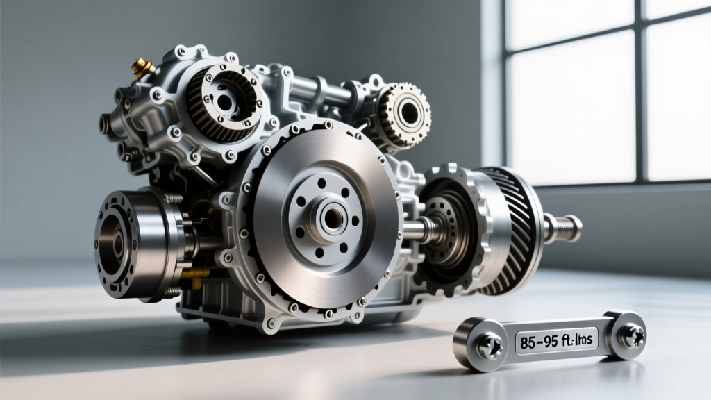
As of 2026, with the widespread integration of high-torque hybrid powertrains and 10-speed automatics like the Ford 10R80 and GM 10L90, the mechanical stresses on the flexplate-to-TC interface have never been higher. Under-torquing leads to elongated holes and sheared bolts; over-torquing strips the threaded nuts welded inside the torque converter cover or warps the flexplate, causing front pump bushing wear and seal leaks.
Below is a reference table detailing OEM specifications for several prevalent transmission platforms. Always consult the specific OEM service manual for your exact application, as revisions occur frequently.
| Transmission Platform | Typical Application | Fastener Qty & Type | Torque Specification | Special Instructions |
|---|---|---|---|---|
| GM 4L60E / 4L80E | Chevy Silverado, Camaro (V8) | 3x M10x1.5 Bolts | 46 lb-ft (62 Nm) | Use blue threadlocker; inspect flexplate for radial cracks. |
| GM 6L80 / 6L90 | Cadillac, Corvette, Trucks | 6x M8 or M10 Bolts | 35 lb-ft (47 Nm) | Ensure converter is fully seated in pump before tightening. |
| Ford 6R80 / 10R80 | F-150, Mustang (Coyote) | 6x Nuts/Studs or Bolts | 35 lb-ft (47 Nm) | Ford often uses nuts on studs welded to the TC. Replace if stretched. |
| ZF 8HP (8HP70/90) | Dodge Ram, BMW, Jaguar | 3x or 4x TTY Bolts | 22 lb-ft + 90° turn | Torque-to-yield. Bolts MUST be replaced upon removal. |
The Role of Fastener Grade and Chemical Lockers
According to fastener engineering data from ARP, the dynamic shear loads placed on flexplate bolts require a minimum of Grade 8 (SAE) or Class 10.9 (Metric) metallurgy. OEM bolts are typically Class 10.9. When replacing lost or damaged hardware, never substitute with standard hardware store Grade 5 bolts, as they will yield under the cyclic loading of TCC lockup.
Furthermore, because the torque converter operates in an environment subjected to extreme thermal cycling and constant oil immersion, mechanical friction alone is often insufficient to maintain clamp load over 150,000 miles. Drivetrain specialists at Sonnax frequently note that flexplate cracking and converter rattle are heavily correlated with loose mounting bolts. Applying a medium-strength threadlocker (such as Loctite 243) is highly recommended for standard bolts, while TTY (Torque-to-Yield) bolts found on ZF and newer Ford applications rely on precise angular yield and generally do not require chemical lockers, provided the threads are clean and lightly oiled for accurate torque readings.
Diagnostic Symptoms of Improper Fastener Torque
When the flywheel to torque converter bolts torque specs are ignored during an engine swap or transmission rebuild, the symptoms rarely manifest immediately. They develop progressively as the vehicle accumulates heat cycles and TCC lockup events.
- TCC Shudder vs. Mechanical Knock: A failing TCC friction liner causes a rhythmic shudder (usually between 1,200 and 1,800 RPM under light throttle). However, if the TC bolts are loose, the converter will physically shift on the flexplate, creating a sharp, metallic 'knock' or 'clunk' during gear changes or when the TCC applies. This is often misdiagnosed as a bad U-joint or engine misfire.
- Front Pump Seal Leaks: If the bolts are unevenly torqued, the flexplate can warp or the torque converter cover can distort. This pushes the converter hub slightly off-center, wearing the front pump bushing and destroying the front transmission seal, leading to low fluid pressure and slipping clutches.
- Elongated Flexplate Holes: Upon removal, a technician will find the bolt holes in the flexplate have become oval-shaped. Once elongated, the flexplate cannot be reused, as the precise concentricity required to balance the rotating assembly is permanently lost.
Installation Best Practices for the Modern Drivetrain
Proper installation requires more than just a torque wrench. The Automatic Transmission Rebuilders Association (ATRA) emphasizes the necessity of verifying torque converter seating depth before the transmission is mated to the engine. If the converter is not fully seated into the transmission oil pump gears (typically requiring three distinct 'clunks' as it passes the turbine shaft splines, stator support, and pump drive), forcing the transmission to the engine block using the bellhousing bolts will preload the flexplate against the converter. Even if you subsequently achieve perfect flywheel to torque converter bolts torque specs, the preloaded state will guarantee premature front pump failure and catastrophic flexplate fatigue.
Always rotate the engine by hand (using a socket on the crankshaft bolt) to access the flexplate bolts through the inspection cover. Torque them in a crisscross pattern to ensure even clamping force across the converter pilot ring. For high-horsepower applications exceeding 600 lb-ft of torque, upgrading to a billet steel flexplate with ARP fasteners is the only reliable method to prevent the flexplate from tearing at the bolt circle under aggressive TCC lockup.
Conclusion
The torque converter vs clutch comparison highlights two entirely different philosophies of power management: fluid dynamics versus mechanical friction. Yet, when the TCC locks, the automatic transmission demands the same mechanical integrity as a manual clutch. Respecting the precise flywheel to torque converter bolts torque specs is the critical link that ensures the hydrodynamic magic of the torque converter translates into reliable, shudder-free forward motion without tearing the rotating assembly apart.