The 'Clean Kitchen' Standard for Drivetrain Teardowns
When you search for clutch kitchen & pour house photos online, you are greeted with images of immaculate, highly organized culinary spaces where every tool has a purpose, surfaces are spotless, and cross-contamination is strictly controlled. As an automotive transmission specialist, I often tell my apprentices that your garage workspace during a manual transmission teardown must mimic that exact level of sterile organization. A messy bench leads to contaminated friction surfaces, dropped hardware, misaligned components, and premature drivetrain failure.
In this comprehensive 2026 step-by-step guide, we will treat your clutch disc and pressure plate inspection with the precision of a high-end culinary workspace. Whether you are rebuilding a classic Ford Toploader, servicing a modern Tremec T-56 Magnum, or replacing a worn dual-mass flywheel (DMF) on a European daily driver, verifying exact tolerances is non-negotiable. Let us break down the inspection process using real-world data, OE specifications, and aftermarket performance benchmarks.
Essential Tooling for Precision Inspection
Before unbolting the pressure plate, gather the following precision instruments. Guessing with a standard tape measure will result in clutch chatter, pedal vibration, and input shaft damage.
- Dial Indicator with Magnetic Base: Resolution of 0.001" (0.025mm) for measuring flywheel runout.
- Digital Calipers & Micrometers: For measuring friction material thickness and diaphragm finger wear.
- Precision Straight Edge & Feeler Gauges: For checking flywheel surface flatness.
- Input Shaft Dummy / Spline Gauge: To verify clutch disc hub spline condition and alignment.
- Torque Wrench (Inch-Pound and Foot-Pound): Calibrated within the last 12 months.
Step 1: Flywheel Mating Surface and Runout Evaluation
The flywheel is the foundation of the clutch assembly. If the mating surface is compromised, no amount of money spent on a premium pressure plate will save the drivetrain from harmonic vibrations.
Visual Inspection: Heat Checking vs. Hard Spots
Superficial heat checking (micro-cracks that resemble a spiderweb) is generally acceptable on cast-iron flywheels, provided they do not catch your fingernail. However, if you observe severe bluing, localized hard spots, or deep thermal scoring, the flywheel must be resurfaced or replaced. According to RAM Clutches Technical Information, hard spots alter the local coefficient of friction, leading to aggressive clutch chatter upon engagement that can eventually shatter ceramic pucks or damage the transmission input shaft bearings.
Measuring Flywheel Runout
Mount your dial indicator to the engine block or bellhousing, positioning the stylus perpendicular to the flywheel friction surface near the outer edge. Rotate the crankshaft two full revolutions. For most GM LS, Ford Coyote, and Chrysler HEMI applications, maximum allowable runout is 0.005" (0.127mm). If runout exceeds this, the flywheel must be resurfaced on a rotary grinder or replaced. Never attempt to shim a modern high-RPM flywheel to correct runout.
Step 2: Pressure Plate Diaphragm and Friction Surface Inspection
The pressure plate is a high-clamp-load spring assembly that endures immense thermal cycling. We inspect three primary areas: the friction face, the diaphragm fingers, and the casting integrity.
Diaphragm Finger Wear Limits
The release bearing rides directly on the tips of the diaphragm spring fingers. Over time, this constant friction cuts grooves into the metal. Using your digital calipers, measure the depth of any wear grooves on the fingers. If the groove depth exceeds 0.020" (0.50mm), the pressure plate must be replaced. Excessive grooving alters the pedal geometry, resulting in a low clutch engagement point and incomplete disengagement, which causes gear grinding during shifts—especially notorious in heavy-duty applications like the ZF S6-650.
Evaluating the Friction Face
Just like the flywheel, the pressure plate friction face must be free of deep gouges and severe bluing. If you are running a centrifugal-assist pressure plate (such as those documented in Centerforce Tech Tips), inspect the internal weight mechanisms. Ensure the pivot pins are secure and the weights move freely without binding, as seized weights will cause uneven clamp load distribution at high RPM.
Step 3: Clutch Disc Friction Material and Hub Assessment
The clutch disc is the sacrificial wear component of the assembly, but premature wear patterns tell a story about the vehicle's hydraulic system, driving habits, or mechanical faults.
Friction Thickness and Rivet Clearance
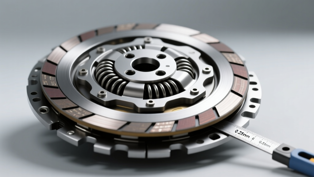
Measure the thickness of the friction material from the steel backing plate to the friction surface. More importantly, measure the clearance from the friction surface to the top of the rivet heads. The industry-standard minimum safe clearance is 0.030" (0.76mm). If the material is worn down to within 0.030" of the rivets, the disc must be replaced. Running a disc too close to the rivets risks scoring the flywheel and pressure plate, turning a $400 clutch job into a $1,200 total assembly replacement.
Marcel Springs and Torsion Dampers
Full-face organic discs utilize 'marcel' (wave) springs between the friction faces to cushion engagement. Press the friction faces together with your thumbs; they should compress smoothly and rebound evenly. If the marcel springs are collapsed or broken, the clutch will engage abruptly, causing driveline shock. Additionally, inspect the torsion damper springs in the center hub. While some rotational free-play is normal, any lateral wobble or broken spring coils mandate immediate replacement.
Spline Wear Verification
Slide the clutch disc onto the actual transmission input shaft (or a dedicated dummy shaft). Hold the shaft horizontally and move the disc up and down. There should be virtually zero lateral play. Excessive spline wear causes the disc to bind on the shaft during disengagement, leading to 'creeping' at stoplights and difficulty shifting into reverse. This is a common failure point in high-torque Tremec T-56 Magnum applications utilizing 1-1/8" 26-spline input shafts.
Expert Insight: Never clean a clutch disc friction surface with brake cleaner or compressed air. Brake cleaner leaves a chemical residue that alters the friction coefficient, while compressed air can embed asbestos or hazardous metallic dust into your workspace. Use only clean, dry lint-free cloths and isopropyl alcohol for the flywheel and pressure plate mating surfaces.
Step 4: Identifying Failure Modes Through Wear Patterns
Before installing new components, diagnose why the old clutch failed to prevent a repeat occurrence.
| Wear Pattern / Symptom | Probable Root Cause | Corrective Action |
|---|---|---|
| Oil-soaked friction material | Rear main seal or transmission input shaft seal leak | Replace seals; clean block mating surfaces; replace disc. |
| Uneven wear (one side thinner) | Bent release fork, worn pivot ball, or misaligned bellhousing | Check bellhousing runout; replace pivot ball and fork. |
| Blueing on flywheel and pressure plate | Riding the clutch pedal or aggressive slip in heavy traffic | Driver education; upgrade to Kevlar/Ceramic for high-heat apps. |
| Broken torsion hub springs | Extreme shock loading, drag launches, or severe engine misfire | Upgrade to heavy-duty hub; fix engine misfire harmonics. |
Step 5: Reassembly Torque Specifications and Best Practices
A meticulous inspection is worthless if the reassembly is botched. Always use new hardware. Reusing stretched flywheel bolts is a recipe for catastrophic crankshaft flange failure.
Flywheel Installation
Clean the crankshaft flange with a Scotch-Brite pad and brake cleaner. Apply a medium-strength threadlocker (e.g., Loctite 243) to the flywheel bolts. For standard GM LS applications (e.g., LQ4, LS3), torque the flywheel bolts to 74 lb-ft in a crisscross pattern. For Ford Modular V8s, refer to the specific TTY (Torque-to-Yield) specs, which often require a two-step torque plus angle sequence (e.g., 59 lb-ft + 90 degrees).
Pressure Plate Alignment and Torque
Use a high-quality steel or brass alignment tool (never rely on cheap plastic tools that can warp and cause binding). Install the pressure plate bolts hand-tight to support the assembly, then torque them down in a multi-pass star pattern. Most standard 10.5" to 12" pressure plates require 30 to 40 lb-ft (always verify with the manufacturer's spec sheet, such as those found in Summit Racing Tech Articles). Over-torquing can warp the pressure plate cover, leading to uneven release and premature bearing wear.
Final Thoughts on Drivetrain Hygiene
Treating your garage with the same respect for cleanliness and organization that you would expect from high-end clutch kitchen & pour house photos is not just about aesthetics; it is a fundamental requirement for mechanical reliability. Dust, grease, and improper tooling are the enemies of hydraulic and friction systems. By adhering to strict measurement tolerances, diagnosing root-cause failure modes, and utilizing precise torque sequences, you ensure that your manual transmission operates smoothly, predictably, and durably for tens of thousands of miles.