The Heavy-Duty Reality: Automotive vs. Bicycle Drivetrains
When enthusiasts discuss bicycle drivetrain maintenance, the conversation usually revolves around chain stretch, cassette wear, and the application of PTFE-based lubricants. It is a world of lightweight alloys, simple hand tools, and low-torque tolerances. However, when you step into the realm of automotive power transfer—specifically the universal joints (U-joints) linking a transmission to a solid axle differential—the stakes change dramatically. Automotive U-joints must transmit hundreds of pound-feet of torque through severe operating angles while enduring high-speed rotational forces. In 2026, with modern trucks and performance vehicles producing unprecedented factory horsepower, understanding the metallurgical and mechanical nuances of U-joint failure is critical for any serious technician or DIYer.
Anatomy of a Spicer Universal Joint
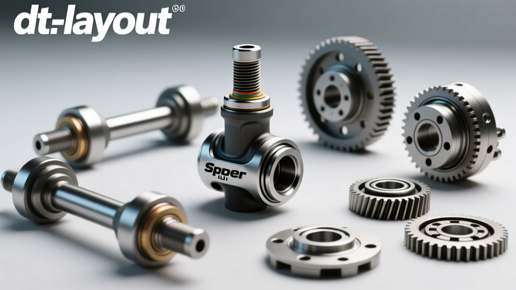
To diagnose a failing U-joint, you must first understand its internal architecture. The most common automotive U-joints are based on the Spicer (Dana) cross-and-bearing design. The assembly consists of a central forged steel cross (or spider), four trunnions, and four needle-bearing caps.
- The Cross: Forged from high-carbon steel, the cross dictates the overall series size (e.g., 1310, 1350, 1410).
- Needle Bearings: Housed inside the caps, these tiny cylindrical bearings reduce friction between the rotating cross and the stationary cap. They rely on a thin film of EP2 lithium-complex grease.
- Seals and Snap Rings: Nitrile rubber lip seals keep contaminants out and grease in, while internal or external snap rings (C-clips) retain the caps within the driveshaft yokes.
Unlike the open chains of a bicycle, these components are sealed and subjected to immense shear stress. When the needle bearings brinell (dent into the cap wall) or the grease breaks down, catastrophic driveline vibration or complete shaft separation can occur.
Diagnostic Matrix: Identifying U-Joint Failure Modes
Driveline NVH (Noise, Vibration, and Harshness) can easily be misdiagnosed as wheel imbalance or worn suspension bushings. Use the following matrix to isolate U-joint specific symptoms.
| Symptom | Operating Condition | Root Cause & Mechanical Failure | Severity |
|---|---|---|---|
| Cyclic Squeak/Chirp | Low speed (5-15 mph) | Grease starvation; needle bearings scoring the cap interior. | Moderate |
| Metallic Clunk | Shifting from Park to Drive/Reverse | Excessive trunnion-to-cap clearance; brinelling of the bearing cup. | High |
| High-Speed Shudder | 50-70 mph under load | Seized U-joint operating out of phase; unequal velocity cancellation failure. | Critical |
| Harmonic Ringing | Coasting / Deceleration | Worn slip-yoke splines or degraded center support bearing isolator. | Moderate |
Pro-Tip: To confirm a worn U-joint without removing the driveshaft, place the vehicle on a lift, leave it in neutral, and rapidly rotate the driveshaft back and forth by hand. Any rotational 'lash' or clicking at the yoke indicates excessive internal clearance.
The Golden Rule: Driveshaft Phase and Indexing
The most common mistake made during U-joint replacement is failing to maintain driveshaft phase. A standard two-joint driveshaft relies on 'velocity cancellation.' Because a single U-joint does not rotate at a constant velocity when operating at an angle, the second U-joint must be perfectly aligned (in phase) with the first to cancel out the speed fluctuations.
If you reinstall the slip-yoke 180 degrees out of phase, the velocity fluctuations will compound rather than cancel, resulting in a violent, floor-shaking vibration at highway speeds. Always use a paint pen or steel punch to mark the relationship between the driveshaft tube and the yoke/slip-yoke before unbolting the U-joint straps.
Technical Replacement Procedure & Torque Specifications
Replacing a U-joint requires more than a hammer and a socket. Using improper tools will collapse the bearing caps, ruining the new component before it is even installed. According to Dana Aftermarket guidelines, a dedicated C-frame press tool (such as the Lisle 35400 or OTC 4516) is mandatory.
Step 1: Extraction and Cleaning
- Remove the driveshaft and mark the phase alignment.
- Remove the external snap rings using 90-degree internal/external pliers.
- Use the C-frame press to push the caps out. Warning: Never strike the cross directly with a steel hammer, as this will mushroom the trunnion ends and bind the needle bearings.
- Clean the yoke bores with a wire brush and brake cleaner. Even a microscopic burr in the yoke bore will prevent the new cap from seating fully, causing the snap ring to fail under load.
Step 2: Pressing the New Cross
- Remove two opposite caps from the new U-joint. Slide the cross into the yoke.
- Start the new caps by hand to ensure they are perfectly square. Press them in using the C-frame tool until there is enough room to install the snap rings.
- Seat the snap rings. If the caps are binding and the joint feels 'tight,' strike the yoke ears sharply with a brass or dead-blow mallet. This relieves the tension on the snap rings and allows the joint to articulate freely.
Step 3: Reinstallation and Torque Specs
Refer to the specific manufacturer data for your application, but standard Spicer torque specifications are as follows:
- 1310 Series Strap Bolts (M8x1.25): 15 - 17 lb-ft
- 1350 Series U-Bolts: 20 - 25 lb-ft
- 1410 Series Strap Bolts: 25 - 30 lb-ft
- Center Support Bearing Bolts: 35 - 45 lb-ft
Note: Always use new strap bolts or apply medium-strength threadlocker (Loctite 243) to reused hardware. Driveline vibration will quickly back out unsecured hardware.
Zerk Fitting Orientation and Grease Purging
If your replacement U-joints feature greaseable Zerks, orientation is a matter of structural integrity. The Zerk fitting must always be positioned on the compression side of the cross during operation, never on the tension side. If placed on the tension side, the centrifugal force and driveline load can pull the fitting out or crack the trunnion.
When greasing, use only an NLGI #2 Lithium-Complex EP grease. Pump grease until you see the old, contaminated grease purge past all four cap seals. Stop immediately once fresh grease purges. Over-greasing will blow out the nitrile lip seals, allowing water and road grit to destroy the needle bearings within a few thousand miles.
Part Numbers, Sizing, and 2026 Cost Analysis
Selecting the correct U-joint series is vital. Upgrading to a larger series (e.g., from 1310 to 1350) requires changing the yokes on the differential and transmission, which is a complex machining job. Stick to the OEM series unless building a dedicated off-road or drag racing vehicle.
Common Spicer Part Numbers (Non-Greaseable / Heavy Duty)
- Spicer 5-153X: 1310 Series (Common on Jeep Wrangler, Ford F-150, GM 1500)
- Spicer 5-793X: 1350 Series (Common on HD trucks, performance applications)
- Spicer 5-3147X: 1410 Series (Heavy commercial, lifted off-road rigs)
Cost Breakdown
As of early 2026, the pricing for quality driveline components remains relatively stable, though labor rates have climbed. A genuine Spicer 1310 U-joint (Part #5-153X) typically retails between $28 and $45 via authorized distributors like Spicer Parts. Avoid unbranded, ultra-cheap offshore alternatives found on generic marketplaces; their needle bearings often lack proper heat treatment and will fail prematurely.
If you are taking the vehicle to a professional driveline shop, expect to pay between $180 and $275 for a single U-joint replacement, which includes the part, shop time on a hydraulic press, and driveshaft balancing verification. For a complete 4WD front and rear driveshaft service (4 to 6 U-joints), total costs can range from $600 to $1,200.
Conclusion: Respect the Driveline
While bicycle drivetrain maintenance teaches the fundamental importance of keeping moving parts clean and lubricated, automotive U-joint service demands a rigorous adherence to torque specs, phase alignment, and metallurgical limits. By utilizing proper pressing tools, verifying yoke bore integrity, and respecting the velocity cancellation principles of the driveshaft, you ensure that the hundreds of horsepower generated by your engine actually reach the pavement safely and smoothly.