The Diagnostic Nightmare: When Speedometer and Pressure Codes Collide
A vehicle rolls into the shop with a non-functional speedometer, harsh shift engagements, and a limp-mode activation. You hook up your advanced bi-directional scan tool and are greeted by a cluster of seemingly unrelated diagnostic trouble codes (DTCs). Specifically, you see a Vehicle Speed Sensor (VSS) or Output Speed Sensor (OSS) code alongside a P0841 or P0843 code, which translates to a transmission fluid pressure sensor switch a circuit range performance fault. Inexperienced technicians might throw parts at both systems, replacing the Transmission Fluid Pressure (TFP) sensor and the speed sensor separately, only to find the issue persists and the codes return within fifty miles.
To understand why speedometer sensor issues are intrinsically linked to transmission pressure circuit faults, we must examine the internal architecture of modern Transmission Control Modules (TCMs) and electro-hydraulic control units. This technical deep-dive explores the shared 5-volt reference circuit dilemma, real-world failure modes in popular transmissions like the GM 6L80 and ZF 8HP, and the precise oscilloscope diagnostics required to isolate the root cause without replacing unnecessary components.
The Shared 5-Volt Reference Architecture Dilemma
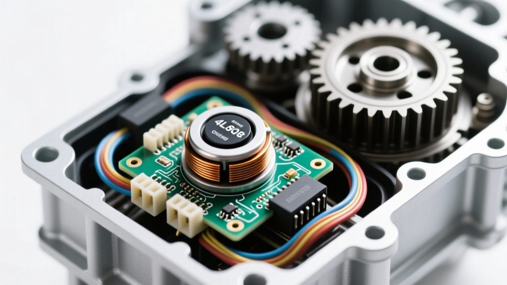
In late-model vehicles, the TCM does not dedicate a completely isolated power supply to every single internal sensor. To reduce wiring harness complexity, minimize electromagnetic interference (EMI), and shrink the internal printed circuit board (PCB) footprint, manufacturers utilize a shared 5-volt reference (5V Ref) bus. In many GM, Ford, and Chrysler applications, the Output Speed Sensor (which feeds the speedometer and shift logic) and the Transmission Fluid Pressure (TFP) sensor share the exact same 5V reference trace and sensor ground return path on the TCM or Mechatronic unit.
When a speedometer sensor experiences an internal short, or its wiring harness chafes against the aluminum valve body, it creates a path of least resistance to ground. This doesn't just kill the speedometer signal; it drags the entire 5V reference bus down. If the 5V bus drops to 2.8V or 3.1V, the TFP sensor—which relies on a precise 5V supply to calculate hydraulic line pressure via a piezoresistive bridge—will output a skewed voltage signal. The TCM interprets this skewed signal as a transmission fluid pressure sensor switch a circuit range performance anomaly, triggering P0841 (Circuit Range/Performance) or P0842 (Circuit Low), even though the pressure sensor itself is perfectly healthy.
Real-World Failure Modes: GM 6L80 and ZF 8HP
GM 6L80 and 6L90 TEHCM Harness Chafing
The GM 6L80 and 6L90 transmissions utilize a Transmission Electro-Hydraulic Control Module (TEHCM) mounted directly inside the transmission pan. The internal wiring harness routes from the TEHCM to the various solenoids and sensors, including the OSS and TFP. A well-documented failure point involves the harness rubbing against the sharp edge of the valve body casting or the filter neck. Over time, the loom degrades, and the 5V reference wire for the speed sensor breaches.
Transmission fluid acts as a dielectric initially, but as it heats up and accumulates metallic clutch debris, it becomes slightly conductive. This creates a high-resistance short to the valve body ground. This manifests as intermittent speedometer dropout when the fluid reaches operating temperature (180°F+), immediately followed by the pressure circuit range performance code. According to SAE International diagnostic standards, high-resistance shorts that only appear at elevated temperatures require active thermal testing to replicate.
ZF 8HP Mechatronic Fluid Ingress
In the ZF 8HP series (found in BMW, Audi, and Chrysler applications), the speed sensors are integrated directly into the Mechatronic unit. The primary failure mode here is not chafing, but O-ring degradation. The Output Speed Sensor seals against the transmission case using a specialized Viton O-ring. If a non-OEM fluid is used, or if the transmission experiences sustained high-temperature events, the O-ring hardens and shrinks.
Pressurized transmission fluid bypasses the seal and wicks into the sensor's electrical connector cavity. This fluid ingress bridges the 5V reference and signal pins, causing the speedometer to read zero while simultaneously corrupting the shared ground plane for the internal pressure transducers. For more details on how fluid contamination affects sensor signaling, refer to OBD-Codes P0841 troubleshooting guidelines.
Diagnostic Data: Voltage Drop and Pinout Specifications
To accurately diagnose this cross-circuit contamination, technicians must move beyond basic OBD-II code reading and perform active circuit testing. Below is the standard 3-wire Hall-effect sensor pinout shared by many OEM speed and pressure sensors.
| Pin | Function | Expected Voltage (KOEO) | Fault State Voltage |
|---|---|---|---|
| Pin 1 | 5V Reference (Shared) | 4.9V - 5.1V | < 3.5V (Indicates short on shared bus) |
| Pin 2 | Signal Return | 0V - 5V (Pulsing) | Stuck at 0V or 5V |
| Pin 3 | Low Reference / Ground | < 0.05V | > 0.1V (High resistance ground) |
Step-by-Step Oscilloscope Isolation Procedure
When faced with a combined speedometer and transmission fluid pressure sensor switch a circuit range performance code, follow this isolation procedure using a digital storage oscilloscope (DSO):
- Step 1: Back-Probe the 5V Reference. Access the TCM or TEHCM connector. Back-probe the 5V reference pin for the OSS. If the voltage reads 2.4V to 3.8V with the key on, engine off (KOEO), you have a shared circuit pull-down.
- Step 2: Isolate the Sensors. Disconnect the TFP sensor. If the 5V reference immediately snaps back to a clean 5.0V, the TFP sensor is internally shorted. If the voltage remains low, reconnect the TFP and disconnect the OSS/VSS.
- Step 3: Confirm the Speed Sensor Fault. If disconnecting the speed sensor restores the 5V reference, you have found your culprit. The speedometer sensor is dragging down the network, causing the phantom pressure code.
- Step 4: Waveform Analysis. If the 5V reference is fine but the speedometer is still erratic, hook the DSO to the signal wire. A healthy Hall-effect speed sensor will produce a crisp square wave ranging from 0V to 5V. If the waveform amplitude drops as the vehicle warms up, or if the square wave corners are rounded (indicating capacitance from fluid ingress), the sensor must be replaced.
Repair Costs, Part Numbers, and Torque Specifications
Proper repair requires OEM-grade components and strict adherence to torque specifications to prevent future fluid leaks or harness damage.
- GM 6L80/6L90 TEHCM Replacement: If the internal harness is damaged beyond repair, the entire TEHCM must be replaced (Part # AC Delco 24253234 or VIN-specific equivalent). Cost: $850 - $1,300 for the part, plus programming. Torque Spec: TEHCM to valve body bolts must be torqued to exactly 10 Nm (89 in-lbs) in the specified star pattern to prevent valve body warpage.
- Standard Output Speed Sensor (e.g., Ford 6R80): Part # Standard Motor Products SLS412 or Motorcraft SW-6925. Cost: $35 - $65. Torque Spec: Hold-down bolt to 11 Nm (97 in-lbs). Always replace the Viton O-ring and lubricate it with clean ATF before installation.
- ZF 8HP Mechatronic Unit: If fluid has breached the internal PCB, the entire Mechatronic unit requires replacement and ZF-approved programming. Cost: $2,800 - $4,200. Torque Spec: Mechatronic to case bolts: 8 Nm (71 in-lbs).
Summary
Speedometer sensor issues and a transmission fluid pressure sensor switch a circuit range performance code are rarely a coincidence. They are symptoms of a shared electrical architecture failing under the harsh thermal and chemical environment inside a modern transmission. By understanding the 5-volt reference bus, utilizing oscilloscope diagnostics, and recognizing model-specific failure points like the GM 6L80 TEHCM harness chafe, technicians can accurately diagnose the root cause on the first attempt, saving customers time and unnecessary parts costs.