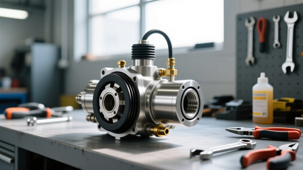
The Diagnostic Dilemma: Slave vs. Master Cylinder
When a manual transmission clutch pedal loses its firm resistance, the immediate culprit is often hidden within the hydraulic system. For automotive technicians and DIY enthusiasts, distinguishing between clutch slave cylinder symptoms and a failing master cylinder is the most critical step in the diagnostic process. Misdiagnosing this system leads to unnecessary parts replacement, wasted labor, and persistent drivability issues. In this comprehensive 2026 comparison and buyer's guide, we will break down the exact failure modes of hydraulic clutch components, compare internal versus external slave architectures, and provide a definitive tutorial on how to install clutch master cylinder assemblies when the diagnosis demands it.
Top 5 Clutch Slave Cylinder Symptoms
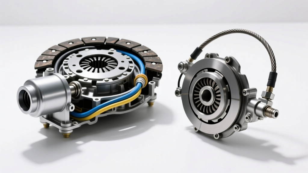
The slave cylinder is the terminal actuator in the hydraulic circuit. Whether it is an external pushrod-style cylinder or an internal Concentric Slave Cylinder (CSC), its failure modes present distinct symptoms that differ subtly from master cylinder degradation.
- 1. Spongy Pedal with Bellhousing Moisture: If the pedal feels spongy and you spot DOT fluid weeping from the bellhousing inspection cover or the transmission-to-engine mating surface, the slave cylinder seals have failed. Internal CSCs leak directly into the bellhousing, while external slaves leak at the pushrod boot.
- 2. Incomplete Clutch Disengagement (Gear Crunch):strong> A failing slave cylinder cannot push the release fork or CSC bearing far enough to fully separate the friction disc from the flywheel. This results in severe grinding when engaging 1st or Reverse gear, even when the pedal is fully depressed.
- 3. Pedal Sticking to the Floorboard: When the internal cup seals of the slave cylinder blow out under high hydraulic pressure, the fluid bypasses the piston. The pedal drops to the floor and will not return, as the hydraulic pressure required to actuate the return spring is lost.
- 4. Sudden Reservoir Drops Without Firewall Leaks: If the brake/clutch fluid reservoir is empty, but the firewall, master cylinder body, and hard lines are completely dry, the fluid has migrated down the hard line and is pooling inside the bellhousing via a ruptured slave cylinder.
- 5. Erratic Engagement Point: A worn slave cylinder bore allows fluid to bypass inconsistently, causing the clutch engagement point to wander from the floorboard to the top of the pedal travel depending on fluid temperature and system pressure.
2026 Buyer's Guide: Internal (CSC) vs. External Slave Cylinders
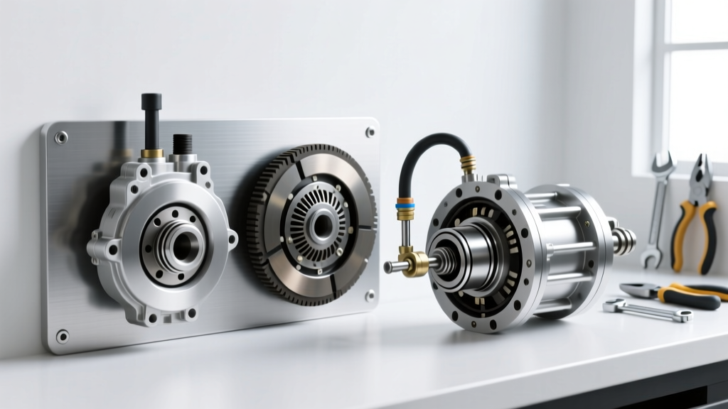
Before purchasing replacement parts, you must identify your transmission's slave architecture. The aftermarket is flooded with inferior components; sticking to OEM-tier manufacturers like FTE Automotive, Sachs, and LuK is non-negotiable for hydraulic longevity.
| Feature | Internal CSC (e.g., Getrag G56, ZF S6-650) | External Slave (e.g., Tremec T56 Magnum, Honda K-Series) |
|---|---|---|
| Design | Combines slave cylinder and throwout bearing into one unit inside the bellhousing. | Separate cylinder mounted externally, actuating a mechanical release fork. |
| Common Part Numbers | LuK LSC108, FTE ZA34044.3.1 | Sachs SH5073, GM 19300056 |
| Replacement Cost (Parts) | $150 - $350 | $45 - $110 |
| Labor Intensity | High (Requires transmission removal, 4-7 hours) | Low (Accessible from engine bay or underneath, 1-2 hours) |
| Bleeding Difficulty | High (Prone to air traps in the CSC bore; often requires reverse bleeding) | Low (Standard gravity or manual bleeding usually suffices) |
Expert Buyer's Tip: When replacing an internal CSC on a Getrag G56 or similar heavy-duty transmission, always replace the braided hydraulic feed line. The OEM plastic quick-connect lines are notorious for becoming brittle from bellhousing heat cycles, leading to catastrophic fluid loss shortly after a new CSC installation.
When the Master Cylinder is the Real Culprit
If your vehicle exhibits a spongy pedal but the slave cylinder and bellhousing are bone dry, the master cylinder is likely failing. Master cylinders suffer from internal bypassing, where the primary cup seal wears against the bore, allowing fluid to slip back into the reservoir rather than traveling down the hard line. Additionally, inspect the pushrod clevis pin at the pedal assembly; excessive wear here mimics hydraulic failure by introducing dead travel into the pedal stroke. Finally, check for firewall flex. In high-torque applications or modified vehicles, the thin sheet metal of the firewall can bend under the heavy foot pressure required for stiff clutch discs, robbing the hydraulic system of its stroke.
Step-by-Step: How to Install Clutch Master Cylinder
If your diagnostic checks confirm master cylinder failure, proper installation is critical to prevent premature seal wear and air ingress. Below is the professional procedure for a firewall-mounted master cylinder (applicable to most late-model GM, Ford, and import platforms).
1. Preparation and Bench Bleeding
Never install a dry master cylinder. The RockAuto catalog and OE service manuals universally mandate bench bleeding. Clamp the new master cylinder (e.g., Aisin CM-003 or FTE KG15032.4.1) in a vise. Fill the integrated reservoir with fresh DOT 4 fluid. Using a blunt punch or specialized bench bleed tool, slowly depress the piston while the outlet port is submerged in fluid. Repeat until zero air bubbles emerge from the piston bore. This prevents air from being pushed deep into the hard line, where it becomes nearly impossible to extract.
2. Firewall Removal and Torque Specifications
Disconnect the negative battery terminal. Remove the lower dash hush panel to access the pedal pushrod. Remove the retaining clip and slide the clevis pin out. Under the hood, place a catch pan below the master cylinder. Use a line wrench to disconnect the hard hydraulic line flare nut—do not use an open-end wrench, as these soft steel nuts round off easily. Unbolt the two or three firewall mounting nuts (typically 10mm or 13mm). Carefully pull the master cylinder forward, ensuring the reservoir doesn't crack against the brake booster.
3. Installation and Hard Line Connection
Transfer any necessary heat shields or pushrod spacers to the new unit. Insert the new master cylinder through the firewall, ensuring the pushrod seats correctly in the pedal clevis. Thread the firewall mounting nuts by hand to prevent cross-threading. Torque the firewall nuts to 15 Nm (11 ft-lbs). Next, thread the hard line flare nut into the master cylinder outlet. This requires a delicate touch; cross-threading will destroy the aluminum housing. Torque the flare nut to 14 Nm (10 ft-lbs).
Bleeding Protocols and Fluid Selection
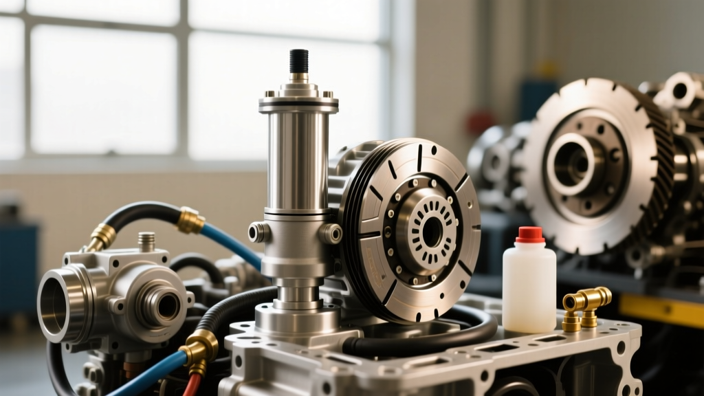
The final step in the installation is bleeding the system. While traditional manual bleeding (pump-and-hold) works for external slaves, internal CSCs often trap air in the concentric bore. For internal systems, reverse bleeding using a Mityvac or Motive Products adapter is the industry standard. By pushing fluid from the slave bleeder screw up to the master reservoir, air naturally rises and escapes.
Regarding fluid, always adhere to the OE specification. Most modern systems require DOT 4 (minimum dry boiling point of 446°F / 230°C) or DOT 5.1 (500°F / 260°C). According to Tremec engineering guidelines, you must never use DOT 5 silicone fluid in a hydraulic clutch system designed for glycol-based fluids. Silicone fluid does not absorb moisture, leading to localized water pooling that will corrode the slave cylinder bore and destroy the seals, resulting in total system failure.