The Intersection of Electro-Hydraulic Failures
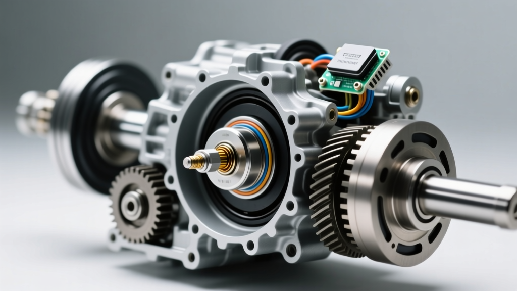
In the modern automotive landscape of 2026, automatic transmissions like the ZF 8HP, GM 6L80, and Ford 6R80 rely on a complex network of electro-hydraulic valves and rotational sensors to deliver seamless gear changes. When a vehicle enters limp mode or exhibits harsh shifting, the culprit is frequently a failing shift solenoid. However, because accessing these solenoids requires dropping the transmission pan and often removing the valve body, technicians and DIYers are inevitably confronted with adjacent components. This leads to a highly searched question in our repair databases: where is a transmission speed sensor located when the valve body is exposed?
This comprehensive guide will walk you through the step-by-step process of shift solenoid problems and replacement, while simultaneously mapping out the location of critical speed sensors to ensure your diagnostic sweep is thorough and efficient.
Differentiating Solenoid Failures from Speed Sensor Faults
Before tearing into the transmission, it is crucial to distinguish between a hydraulic control issue (solenoids) and a data-logging issue (speed sensors). A failing shift solenoid will manifest as physical drivability complaints: harsh 1-2 upshifts, delayed reverse engagement, or the transmission defaulting to 3rd gear limp mode. Conversely, a failing Input or Output Speed Sensor will trigger RPM mismatch codes (such as P0717 or P0720). The TCM will detect that the engine RPM does not correlate with the transmission output shaft speed, often causing the speedometer to drop to zero and the torque converter clutch to lock up erratically. Understanding this distinction prevents unnecessary valve body removal when a simple exterior speed sensor replacement is all that is required.
Step 1: Accurate Diagnostics Before Teardown
Never replace a shift solenoid based on shift quality alone. You must verify the electrical and hydraulic integrity of the circuit. Shift solenoid issues typically trigger OBD-II codes in the P0750 to P0770 range. For instance, a P0750 code indicates a Shift Solenoid A circuit malfunction.
- Electrical Testing: Use a digital multimeter to check solenoid resistance at the transmission harness connector. Standard on/off shift solenoids (like those in the GM 4L60E) should read between 19 and 24 ohms. Variable Force Solenoids (VFS) in ZF and Ford units typically read much lower, between 1.5 and 5.0 ohms.
- Wiring Inspection: Check for chafed wires near the transmission case pass-through connector, a known failure point for fluid ingress that wicks ATF into the Transmission Control Module (TCM).
Step 2: Pan Removal and Fluid Inspection
Before unbolting the valve body, the transmission fluid must be drained and inspected. The condition of the fluid provides vital clues about internal hard-part damage.
- Ensure the vehicle is on a level lift and the transmission is at operating temperature (typically 185°F - 200°F) for an accurate fluid level check later.
- Remove the perimeter pan bolts. For transmissions with a reusable RTV seal (like many Chrysler 8-speed units), carefully break the seal with a plastic trim tool to avoid scoring the aluminum mating surfaces.
- Inspect the pan magnets. A fine metallic paste is normal clutch wear material. However, if you find chunky metal shards or brass-colored bushing fragments, a simple solenoid replacement will not save the transmission; a full rebuild is required.
Step 3: Shift Solenoid Replacement Procedure
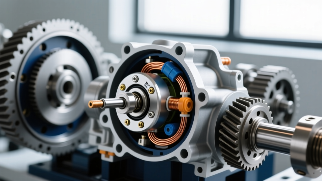
Once the valve body is exposed, you can access the individual solenoids. Note that on some modern units (like the GM 6L80/8L90), the solenoids are integrated into the TEHCM (Transmission Electro-Hydraulic Control Module) and cannot be serviced individually without replacing the entire assembly. However, on units like the Ford 6R80 or ZF 6HP26, individual solenoid replacement is standard practice.
Expert Tip: Never reuse solenoid O-rings. Even if they look pristine, the neoprene material compresses and degrades over time. Always lubricate new O-rings with fresh, clean ATF before installation to prevent pinching and immediate pressure leaks upon startup.
Carefully unclip the electrical harness retaining tabs. Use a small pick to release the solenoid retaining clip, then twist and pull the solenoid straight out of its bore. Insert the new OEM solenoid, ensuring it seats fully with a firm click. Re-secure the retaining clip and reconnect the harness.
Valve Body Access: Where is a Transmission Speed Sensor Located?
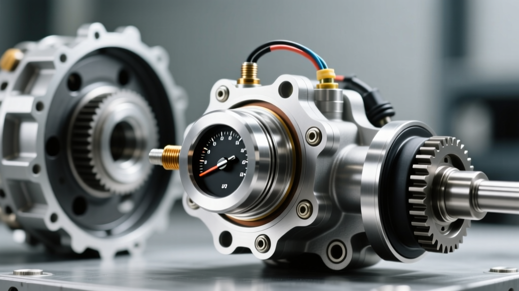
With the pan off and the valve body exposed, it is the perfect time to address the secondary diagnostic question: where is a transmission speed sensor located? The answer depends heavily on your specific transmission architecture, but they generally fall into two categories:
1. Externally Mounted Speed Sensors
On many traditional rear-wheel-drive transmissions (such as the GM 4L60E or Ford 5R55), the Output Speed Sensor (OSS) is not on the valve body at all. It is threaded into the exterior rear extension housing or tail shaft, reading a reluctor ring on the output carrier. The Input Speed Sensor (ISS) is often located under the front pump cover or threaded into the upper case.
2. Internally Integrated Speed Sensors
In modern mechatronic units like the ZF 8HP or Ford 10R80, the speed sensors are integrated directly into the valve body assembly or the external wiring harness frame that wraps around the solenoids. According to Sonnax transmission resources, attempting to pry these sensors out of a mechatronic plate can crack the delicate plastic housing or sever the micro-wiring. If an internal speed sensor fails on these units, you are often required to replace the entire wiring harness frame or the complete mechatronic valve body assembly.
2026 Cost Breakdown and Torque Specifications
Precision is paramount when reassembling the transmission. Overtorquing valve body bolts will warp the aluminum separator plates, causing cross-leaking that mimics a bad solenoid. Below is a reference table for common service data based on current 2026 aftermarket and OEM pricing.
| Component / Spec | GM 4L60E | Ford 6R80 / ZF 6HP | Estimated OEM Part Cost |
|---|---|---|---|
| Shift Solenoid Resistance | 19 - 24 Ohms | 1.5 - 5.0 Ohms (VFS) | $25 - $85 per solenoid |
| Valve Body Bolt Torque | 11 Nm (97 in-lbs) | 8 - 10 Nm (71-89 in-lbs) | N/A |
| Pan Bolt Torque | 15 Nm (11 ft-lbs) | 12 Nm (106 in-lbs) | N/A |
| Fluid Capacity (Dry Fill) | 12 Quarts (Dexron VI) | 13.1 Quarts (Mercon LV) | $8 - $14 per quart |
Fluid Selection and Temperature Compensation
Modern solenoids are calibrated for specific fluid viscosities. Using the incorrect ATF will alter the hydraulic apply times, causing the TCM to throw shift timing codes even with brand-new solenoids. For example, GM units require Dexron VI, which has a specific shear-stability profile, while Ford and ZF units rely on Mercon LV or ZF LifeguardFluid 8. Always verify the fluid specification stamped on the dipstick or in the OEM service manual before filling. You can source exact-match fluids and components via suppliers like RockAuto.
Step 4: TCM Adaptation and Relearn Protocols
Replacing the hardware is only half the battle. The Transmission Control Module (TCM) relies on adaptive shift tables that have learned to compensate for your old, sticky solenoids. If you do not reset these adaptions, the new solenoids will command incorrect line pressures, resulting in harsh, banging shifts or immediate flare-ups.
- OBD-II Scanner Requirement: You must use a bi-directional scan tool capable of accessing the TCM. Standard code readers cannot perform this function.
- Reset Procedure: Navigate to the TCM special functions menu and select 'Reset Shift Adaptations' or 'Clear Keep Alive Memory (KAM)'.
- The Relearn Drive: Perform the manufacturer-specific relearn drive cycle. This usually involves driving the vehicle on a flat, straight road, accelerating at light throttle (15-20% TPS) through all gears, and allowing the vehicle to coast down to a stop. The transmission fluid must be above 160°F to properly calibrate the downshift and torque converter clutch (TCC) apply rates.
By combining a meticulous shift solenoid replacement with a thorough inspection of the speed sensor locations, you ensure the entire electro-hydraulic network is operating flawlessly, extending the life of your drivetrain for years to come.