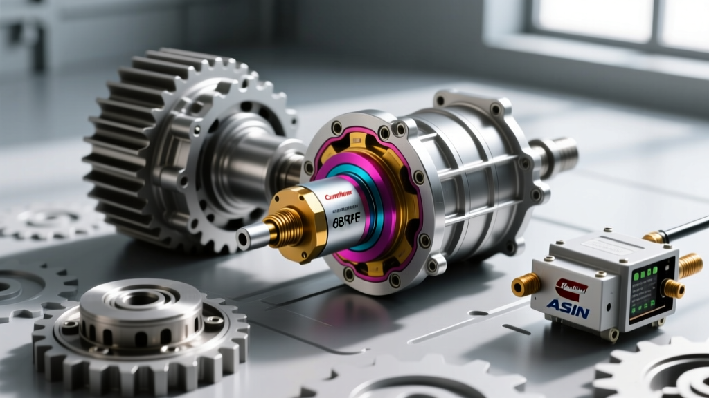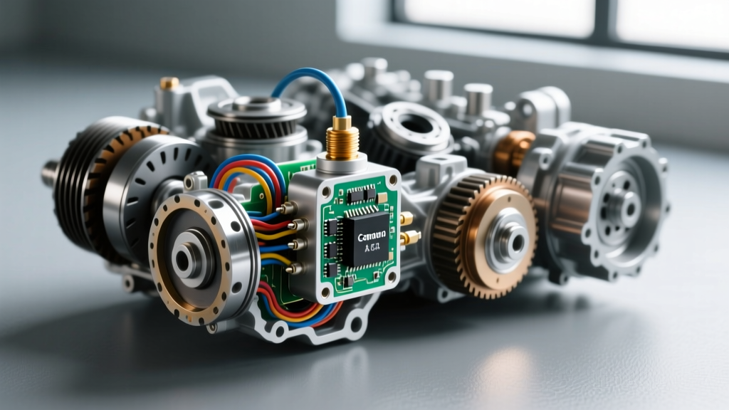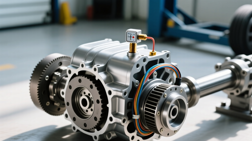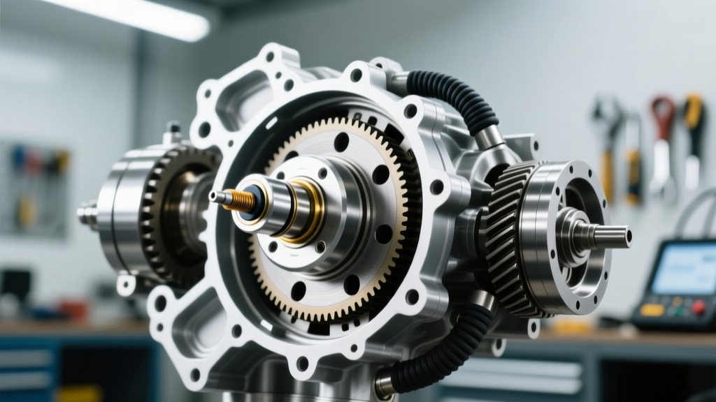
The ABS-TCM Connection: Answering the Core Question
When diagnosing erratic shifting, harsh engagements, or unexpected limp-mode activations, technicians and DIY enthusiasts frequently ask: can wheel speed sensor affect transmission operation? The short answer is yes, but the mechanism is often misunderstood. Modern vehicles utilize a high-speed Controller Area Network (CAN bus) to share data between the Anti-lock Braking System (ABS) module and the Transmission Control Module (TCM).
The TCM relies on wheel speed data to calculate vehicle speed, determine torque converter clutch (TCC) slip, and execute precise shift scheduling. If a wheel speed sensor (WSS) fails or drops its signal intermittently, the ABS module broadcasts a fault over the CAN bus. Upon receiving this invalid data, the TCM will often default to a fail-safe shift map. This results in delayed upshifts, harsh downshifts, and the disabling of the torque converter clutch lockup to protect the drivetrain. Therefore, before tearing into the transmission pan, a proper diagnostic scan of the ABS and chassis modules is mandatory.
However, if the ABS modules report no faults and the CAN bus is healthy, the culprit is almost certainly a dedicated transmission speed sensor—specifically the Input Speed Sensor (ISS) or Output Speed Sensor (OSS). Below, we detail the expert-level diagnosis and replacement protocols for these critical internal sensors.
Input vs. Output: Understanding Transmission Speed Sensors
Automatic transmissions typically utilize two primary speed sensors to manage hydraulic line pressure and shift timing:
- Input Speed Sensor (ISS): Also known as the turbine speed sensor, it monitors the rotational speed of the transmission's input shaft (connected to the torque converter). The TCM compares ISS data against engine RPM to calculate TCC slip.
- Output Speed Sensor (OSS): Monitors the rotational speed of the output shaft or ring gear. This data is used to determine actual vehicle speed and gear ratio.
If the TCM detects a discrepancy between the ISS and OSS readings that does not match the commanded gear ratio, it will trigger codes such as P0731 (Gear 1 Incorrect Ratio) or P0732 (Gear 2 Incorrect Ratio), eventually leading to a P0700 (Transmission Control System Malfunction) and limp-home mode.
Magnetic Reluctance vs. Hall-Effect Technology
Older transmissions (like the GM 4L60E) predominantly used magnetic reluctance sensors. These passive sensors generate an alternating current (AC) voltage sine wave as a toothed reluctor ring passes by the magnetic core. The frequency and amplitude increase with shaft speed.
Modern 8-speed, 9-speed, and 10-speed transmissions (such as the ZF 8HP and GM 10L80) utilize Hall-effect sensors. These active sensors require a 5V to 12V reference voltage from the TCM and output a crisp digital square wave. Hall-effect sensors are highly accurate even at near-zero RPMs, which is essential for the micro-slip control required in modern lockup clutches.
Step-by-Step Diagnostic Protocol
Before ordering parts, verify the failure with empirical data. Relying solely on OBD2 codes like P0715 (Input/Turbine Speed Sensor Circuit) or P0720 (Output Speed Sensor Circuit) is a rookie mistake. These codes indicate a circuit fault, not necessarily a dead sensor.
1. Visual and Fluid Inspection
Drop the transmission pan and inspect the fluid. If the fluid is heavily contaminated with metallic clutch material or ferrous debris, the magnetic tip of the speed sensor may be coated in sludge, dampening the magnetic field and causing signal dropout. Clean the sensor tip with a lint-free cloth and isopropyl alcohol before condemning the component.
2. Multimeter and Oscilloscope Testing
For magnetic reluctance sensors, disconnect the harness and measure resistance across the sensor pins. According to AA1Car Automotive Library, typical resistance ranges between 1,000 and 2,500 ohms at room temperature. An infinite reading indicates an open internal coil; a near-zero reading indicates a short.
For Hall-effect sensors, a multimeter is insufficient. You must back-probe the connector with a PicoScope or equivalent automotive oscilloscope while the vehicle is on a lift and the drive wheels are spinning. You are looking for a clean, square 5V/0V digital waveform. Any rounding of the corners or voltage drops below 4.5V indicates a failing sensor or a compromised TCM driver circuit.
Expert Tip: Never pierce the wire insulation with a test light or standard multimeter probe to back-probe a transmission sensor. The resulting micro-puncture will allow moisture to wick into the wiring harness via capillary action, destroying the TCM pins within months. Always use proper T-pin back-probes inserted into the rear of the connector.
Replacement Best Practices & Torque Specifications
Replacing a transmission speed sensor requires meticulous attention to torque specifications and sealing surfaces. An over-torqued sensor can warp the internal plastic housing or crack the sensor body, leading to immediate fluid leaks and catastrophic failure.
| Transmission Model | Sensor Type | OEM Part Number | Torque Specification | Estimated Part Cost (2026) |
|---|---|---|---|---|
| GM 6L80 / 6L90 | Output Speed (OSS) | ACDelco 24227797 | 8 Nm (71 lb-in) | $45 - $65 |
| Ford 6R80 | Output Speed (OSS) | Motorcraft SW-7269 | 8 Nm (71 lb-in) | $50 - $75 |
| Toyota A750E (Aisin) | Input Speed (ISS) | Toyota 89413-30040 | 10 Nm (89 lb-in) | $85 - $115 |
| Chrysler 8HP (ZF) | Turbine Speed | Integrated in Mechatronic | N/A (Sleeve Seal Only) | $1,200+ (Mechatronic) |
Note on ZF 8HP Units: In many modern ZF 8-speed applications, the internal speed sensors are integrated directly into the Mechatronic (valve body/TCM) assembly. While some aftermarket kits exist to splice and replace individual Hall-effect sensors, OEM protocol dictates replacing the entire Mechatronic unit or utilizing specialized ZF-approved repair sleeves to maintain IP67 waterproofing inside the fluid-filled pan.
O-Ring and Seal Rehabilitation
Every external transmission speed sensor utilizes an O-ring to seal against pressurized transmission fluid (which can exceed 150 PSI at the lubrication circuits). Never reuse the old O-ring. Lubricate the new OEM O-ring with fresh, vehicle-specific ATF (e.g., Dexron ULV or Mercon LV) before installation. Installing the sensor dry can cause the O-ring to pinch, roll, or shear during insertion, resulting in an external weep that mimics a rear main seal leak.
Wiring Harness and Connector Degradation
In 60% of P0720 and P0715 diagnoses, the sensor itself is perfectly functional, and the fault lies in the wiring harness. The transmission main harness exits the case via a multi-pin pass-through connector (often located on the side of the transmission pan or bellhousing). This area is subjected to extreme thermal cycling, road salt, and high-frequency vibration.
Inspect the connector for 'green death' (copper oxide corrosion). If corrosion is present on the TCM side of the harness, you must perform a pigtail repair. Cut back the harness a minimum of 4 inches from the connector to reach clean, unoxidized copper. Use heat-shrink butt splices with integrated solder rings and seal the exterior with dielectric silicone. According to diagnostic standards highlighted by Transmission Digest, failing to address harness tension and corrosion will result in a 'ghost' code returning within 500 miles of sensor replacement.
Post-Replacement TCM Adaptation Procedures
Replacing the sensor is only half the job. The TCM stores long-term adaptive memory regarding shift timing and TCC slip based on the degraded signal of the failing sensor. If you do not reset these adaptives, the transmission will continue to shift harshly or slip, potentially causing the customer to misdiagnose the repair.
Using a bi-directional professional scan tool (such as an Autel MaxiSys or Snap-on Zeus), navigate to the TCM special functions menu and execute the following:
- Clear DTCs and Reset Adaptives: Wipe the Keep Alive Memory (KAM) specifically for the transmission module.
- Perform TCC Relearn: Most manufacturers require a specific drive cycle to relearn torque converter slip. This usually involves driving the vehicle at a steady 45-55 MPH in top gear with the brake pedal lightly dragged (to induce slip) until the transmission fluid temperature reaches exactly 70°C to 90°C (158°F to 194°F).
- Verify Live Data: Monitor the ISS and OSS PID data simultaneously. At a steady cruise, the RPM delta between the ISS and OSS must perfectly match the mathematical gear ratio of the commanded gear. For example, if 4th gear has a ratio of 1.15:1, and the OSS reads 1,500 RPM, the ISS should read approximately 1,725 RPM.
By understanding the intricate relationship between chassis speed data and internal transmission telemetry, technicians can avoid unnecessary teardowns and deliver definitive, long-lasting repairs. For further code-specific troubleshooting, resources like the OBD-Codes P0720 Reference Guide remain invaluable for cross-referencing manufacturer-specific technical service bulletins (TSBs).